Toyota Sienna Service Manual: Short to GND in Curtain Shield Squib RH Circuit
DTC B1162/81 Short to GND in Curtain Shield Squib RH Circuit
DESCRIPTION
The curtain shield squib RH circuit consists of the center airbag sensor assembly and the curtain shield airbag assembly RH.
The circuit instructs the SRS to deploy when deployment conditions are met.
DTC B1162/81 is recorded when a short to ground is detected in the curtain shield squib RH circuit.
|
DTC No. |
DTC Detecting Condition |
Trouble Area |
|
B1162/81 |
|
|
INSPECTION PROCEDURE
HINT:
- Perform the simulation method by selecting the "check mode" (signal check) with the intelligent tester (8).
- After selecting the "check mode" (signal check), perform the simulation method by wiggling each connector of the airbag system or driving the vehicle on a city or rough road
1 CHECK CURTAIN SHIELD AIRBAG ASSEMBLY RH (CURTAIN SHIELD SQUIB RH)
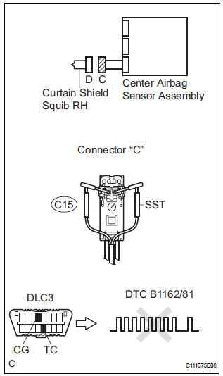
- Turn the ignition switch to the LOCK position.
- Disconnect the negative (-) terminal cable from the battery, and wait for at least 90 seconds.
- Disconnect the connectors from the curtain shield airbag assembly RH.
- Connect the white wire side of SST (resistance 2.1 Ω) to the floor wire No. 2.
CAUTION: Never connect a tester to the curtain shield airbag assembly RH (Curtain shield squib RH) for measurement, as this may lead to a serious injury due to airbag deployment.
NOTICE: Do not forcibly insert the SST into the terminals of the connector when connecting.
Insert the SST straight into the terminals of the connector.
SST 09843-18060
- Connect the negative (-) terminal cable to the battery, and wait for at least 2 seconds.
- Turn the ignition switch to the ON position, and wait for at least 60 seconds.
- Clear the DTCs stored in memory (5).
- Turn the ignition switch to the LOCK position.
- Turn the ignition switch to the ON position, and wait for at least 60 seconds.
- Check the DTCs (5).
OK: DTC B1162/81 is not output. HINT: Codes other than DTC B1162/81 may be output at this time, but they are not related to this check.
 Go to step 2

REPLACE CURTAIN SHIELD AIRBAG ASSEMBLY RH
2 CHECK FLOOR WIRE NO.2 (CURTAIN SHIELD SQUIB RH CIRCUIT)
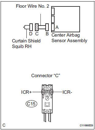
- Turn the ignition switch to the LOCK position.
- Disconnect the negative (-) terminal cable from the battery, and wait for at least 90 seconds.
- Disconnect the SST (resistance 2.1 Ω) from the floor wire No. 2.
- Disconnect the connector from the center airbag sensor assembly.
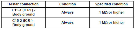
- Measure the resistance according to the value(s) in the table below.
Standard resistance
 REPAIR OR REPLACE FLOOR WIRE
NO.2
REPAIR OR REPLACE FLOOR WIRE
NO.2

3 CHECK CENTER AIRBAG SENSOR ASSEMBLY
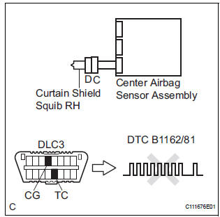
- Connect the connectors to the curtain shield airbag assembly RH and the center airbag sensor assembly.
- Connect the negative (-) terminal cable to the battery, and wait for at least 2 seconds.
- Turn the ignition switch to the ON position, and wait for at least 60 seconds.
- Clear the DTCs stored in memory (5).
- Turn the ignition switch to the LOCK position.
- Turn the ignition switch to the ON position, and wait for at least 60 seconds.
- Check the DTCs (5).
OK: DTC B1162/81 is not output. HINT: Codes other than DTC B1162/81 may be output at this time, but they are not related to this check.
 REPLACE CENTER AIRBAG SENSOR
ASSEMBLY
REPLACE CENTER AIRBAG SENSOR
ASSEMBLY

USE SIMULATION METHOD TO CHECK
 Open in Curtain Shield Squib RH Circuit
DTC B1161/84 Open in Curtain Shield Squib RH Circuit
DESCRIPTION
The curtain shield squib RH circuit consists of the center airbag sensor
assembly and the curtain shield
airbag assembly RH.
Th ...
 Short to B+ in Curtain Shield Squib RH Circuit
DTC B1163/82 Short to B+ in Curtain Shield Squib RH Circuit
DESCRIPTION
The curtain shield squib RH circuit consists of the center airbag sensor
assembly and the curtain shield
airbag assembly RH ...
Other materials:
ECM Power Source Circuit
DESCRIPTION
When the ignition switch is turned to the ON position, the battery voltage is
applied to terminal IGSW of
the ECM. The ECM MREL output signal causes a current to flow to the coil,
closing the contacts of the EFI
relay and supplying power to terminal +B of the ECM.
If the igniti ...
Correct driving posture
Adjust the angle of the seatback so that you are sitting straight up and
so that you do not have to lean forward to steer.
Adjust the seat so that you can depress the pedals fully and so that
your arms bend slightly at the elbow when gripping the steering wheel.
Lock the head rest ...
Speed sensor check (when using intelligent tester)
(a) Check the backward signal.
(1) Drive the vehicle in reverse for more than 1
second at 3 km/h (2 mph) or higher.
HINT:
Drive the vehicle in reverse and check the speed
sensor signal. Note that the signal check cannot
be completed if the vehicle speed is 45 km/h (28
mph) or more.
(b) Che ...
