Toyota Sienna Service Manual: Camshaft Position "A" Actuator Circuit
DESCRIPTION
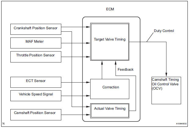
The Variable Valve Timing (VVT) system includes the ECM, Oil Control Valve (OCV) and VVT controller.
The ECM sends a target duty-cycle control signal to the OCV. This control signal regulates the oil pressure supplied to the VVT controller. Camshaft timing control is performed according to engine operating conditions such as intake air volume, throttle valve position and engine coolant temperature.
The ECM controls the OCV, based on the signals transmitted by several sensors. The VVT controller regulates the intake camshaft angle using oil pressure through the OCV. As a result, the relative positions of the camshaft and crankshaft are optimized, the engine torque and fuel economy improves, and the exhaust emissions decrease under overall driving conditions. The ECM detects the actual intake valve timing using signals from the camshaft and crankshaft position sensors, and performs feedback control.
This is how the target intake valve timing is verified by the ECM.
MONITOR DESCRIPTION
After the ECM sends the "target" duty-cycle signal to the OCV, the ECM monitors the OCV current to establish an "actual" duty-cycle. The ECM detects a malfunction and sets a DTC when the actual dutycycle ratio varies from the target duty-cycle ratio.
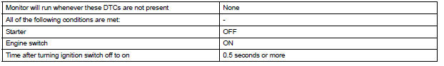
MONITOR STRATEGY
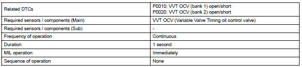
TYPICAL ENABLING CONDITIONS
TYPICAL MALFUNCTION THRESHOLDS
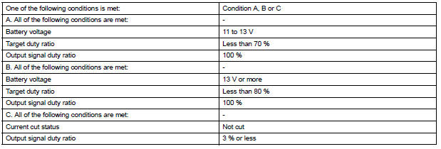
COMPONENT OPERATING RANGE

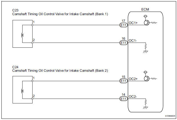
WIRING DIAGRAM
INSPECTION PROCEDURE
HINT:
- If DTC P0010 is displayed, check the intake camshaft circuit for the right bank VVT system.
- Bank 1 refers to the bank that includes cylinder No. 1.
- If DTC P0020 is displayed, check the intake camshaft circuit for the left bank VVT system.
- Bank 2 refers to the bank that does not include cylinder No. 1.
- Read freeze frame data using the intelligent tester. The ECM records vehicle and driving condition information as freeze frame data the moment a DTC is stored. When troubleshooting, freeze frame data can be helpful in determining whether the vehicle was running or stopped, whether the engine was warmed up or not, whether the air-fuel ratio was lean or rich, as well as other data recorded at the time of a malfunction.
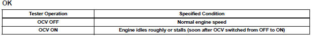
1 PERFORM ACTIVE TEST BY CAMSHAFT TIMING OIL CONTROL VALVE ASSEMBLY (OCV)
(a) Connect the intelligent tester to the DLC3.
(b) Start the engine and turn the tester on.
(c) Warm up the engine.
(d) On the tester, enter the following menus: DIAGNOSIS / ENHANCED OBD II / ACTIVE TEST / VVT CTRL B1 or VVT CTRL B2.
(e) Check the engine speed while operating the Oil Control Valve (OCV) using the tester.

2 INSPECT CAMSHAFT TIMING OIL CONTROL VALVE ASSEMBLY
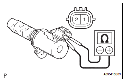
(a) Disconnect the C23 or C24 camshaft timing oil control valve (OCV) connector.
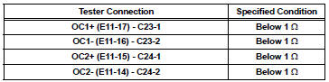
(b) Measure the resistance according to the value(s) in the table below.
Standard resistance 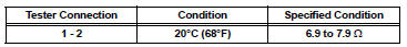
(c) Reconnect the OCV connector.

3 CHECK HARNESS AND CONNECTOR (OCV - ECM)
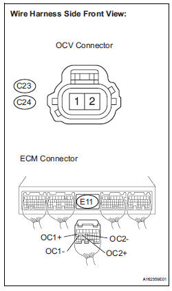
(a) Disconnect the C23 or C24 camshaft timing oil control valve (OCV) connector.
(b) Disconnect the E11 ECM connector.
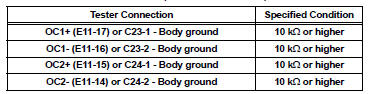
(c) Measure the resistance according to the value(s) in the table below.
Standard resistance (Check for open)
Standard resistance (Check for short)
(d) Reconnect the OCV connector.
(e) Reconnect the ECM connector.


REPLACE ECM (See page ES-498)
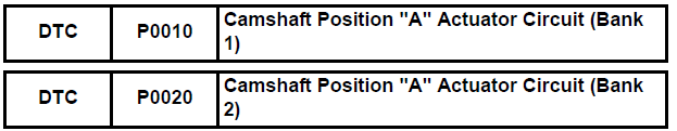
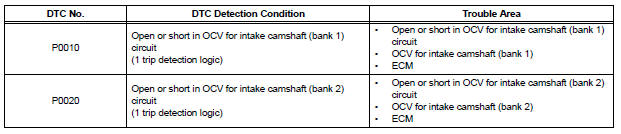
 Diagnostic trouble code chart
HINT:
The parameters listed in the chart may not confirm exactly to
those read during the DTC check due to the type of
instrument or other factors.
If a trouble code is displayed during the DTC ...
 Camshaft Position "A" - Timing Over
HINT:
If DTC P0011, P0012, P0021 or P0022 is present, check the VVT (Variable Valve
Timing) system.
DESCRIPTION
Refer to DTC P0010 (See page ES-75).
DTC No.
DTC Detection Condition ...
Other materials:
DVD Error/ Excess Current/ Tray Insertion / Ejection Error
DTC 44-44 DVD Error
DTC 44-48 Excess Current
DTC 44-50 Tray Insertion / Ejection Error
DESCRIPTION
DTC No.
DTC Detection Condition
Trouble Area
44-44
Operation error in the DVD mechanism
Television display assembly
44-48
Excess current is prese ...
Check that initialization has been completed
(a) Confirm that the data of tire pressure of all tires are
displayed on the intelligent tester screen.
Tester Display
Measurement Item/Range
Normal Condition
Diagnostic Note
TIREPRESS1
ID1 tire inflation pressure (Absolute
pressure) /
min.: 100 kPa (1 kgf/cm2, 14 ...
Short to B+ in CAN Bus Line
DESCRIPTION
A short to B+ is suspected in the CAN bus wire when the resistance between
terminals 6 (CANH) and 16
(BAT), or terminals 14 (CANL) and 16 (BAT) of the DLC3 is below 6 kΩ.
Symptom
Trouble Area
The resistance between terminals 6 (CANH) and 16 (BAT), or
...
