Toyota Sienna Service Manual: Short to B+ in Curtain Shield Squib RH Circuit
DTC B1163/82 Short to B+ in Curtain Shield Squib RH Circuit
DESCRIPTION
The curtain shield squib RH circuit consists of the center airbag sensor assembly and the curtain shield airbag assembly RH.
The circuit instructs the SRS to deploy when deployment conditions are met.
DTC B1163/82 is recorded when a short to B+ is detected in the curtain shield squib RH circuit
|
DTC No. |
DTC Detecting Condition |
Trouble Area |
|
B1163/82 |
|
|
INSPECTION PROCEDURE
HINT:
- Perform the simulation method by selecting the "check mode" (signal check) with the intelligent tester (8).
- After selecting the "check mode" (signal check), perform the simulation method by wiggling each connector of the airbag system or driving the vehicle on a city or rough road
1 CHECK CURTAIN SHIELD AIRBAG ASSEMBLY RH (CURTAIN SHIELD SQUIB RH)
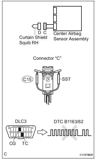
- Turn the ignition switch to the LOCK position.
- Disconnect the negative (-) terminal cable from the battery, and wait for at least 90 seconds.
- Disconnect the connectors from the curtain shield airbag assembly RH.
- Connect the white wire side of SST (resistance 2.1 Ω) to the floor wire No. 2.
CAUTION: Never connect a tester to the curtain shield airbag assembly RH (Curtain shield squib RH) for measurement, as this may lead to a serious injury due to airbag deployment.
NOTICE: Do not forcibly insert the SST into the terminals of the connector when connecting.
Insert the SST straight into the terminals of the connector.
SST 09843-18060
- Connect the negative (-) terminal cable to the battery, and wait for at least 2 seconds.
- Turn the ignition switch to the ON position, and wait for at least 60 seconds.
- Clear the DTCs stored in memory (5).
- Turn the ignition switch to the LOCK position.
- Turn the ignition switch to the ON position, and wait for at least 60 seconds.
- Check the DTCs
OK: DTC B1163/82 is not output. HINT: Codes other than DTC B1163/82 may be output at this time, but they are not related to this check.
 Go to step 2

REPLACE CURTAIN SHIELD AIRBAG ASSEMBLY RH
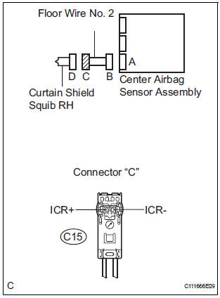
2 CHECK FLOOR WIRE NO.2 (CURTAIN SHIELD SQUIB RH CIRCUIT)
- Turn the ignition switch to the LOCK position.
- Disconnect the negative (-) terminal cable from the battery, and wait for at least 90 seconds.
- Disconnect the SST (resistance 2.1 Ω) from the floor wire No. 2.
- Disconnect the connector from the center airbag sensor assembly.
- Connect the negative (-) terminal cable to the battery, and wait for at least 2 seconds.
- Turn the ignition switch to the ON position.
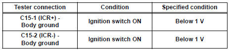
- Measure the voltage according to the value(s) in the table below.
Standard voltage
 REPAIR OR REPLACE FLOOR WIRE
NO.2
REPAIR OR REPLACE FLOOR WIRE
NO.2

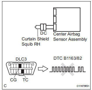
3 CHECK CENTER AIRBAG SENSOR ASSEMBLY
- Turn the ignition switch to the LOCK position.
- Disconnect the negative (-) terminal cable from the battery, and wait for at least 90 seconds.
- Connect the connectors to the curtain shield airbag assembly RH and the center airbag sensor assembly.
- Connect the negative (-) terminal cable to the battery, and wait for at least 2 seconds.
- Turn the ignition switch to the ON position, and wait for at least 60 seconds.
- Clear the DTCs stored in memory (5).
- Turn the ignition switch to the LOCK position.
- Turn the ignition switch to the ON position, and wait for at least 60 seconds.
- Check the DTCs (5).
OK: DTC B1163/82 is not output. HINT: Codes other than code B1163/82 may be output at this time, but they are not related to this check.
 REPLACE CENTER AIRBAG SENSOR
ASSEMBLY
REPLACE CENTER AIRBAG SENSOR
ASSEMBLY

USE SIMULATION METHOD TO CHECK
 Short to GND in Curtain Shield Squib RH Circuit
DTC B1162/81 Short to GND in Curtain Shield Squib RH Circuit
DESCRIPTION
The curtain shield squib RH circuit consists of the center airbag sensor
assembly and the curtain shield
airbag assembly R ...
 Short in Curtain Shield Squib LH Circuit
DTC B1165/87 Short in Curtain Shield Squib LH Circuit
DESCRIPTION
The curtain shield squib LH circuit consists of the center airbag sensor
assembly and the curtain shield
airbag assembly LH.
T ...
Other materials:
Removal
1. REMOVE REAR DOOR SCUFF PLATE
2. REMOVE REAR DOOR WEATHERSTRIP
3. REMOVE BACK DOOR WEATHERSTRIP
4. REMOVE BACK DOOR SCUFF PLATE
5. REMOVE FRONT QUARTER TRIM PANEL ASSEMBLY
Remove the floor anchor cover.
Remove the bolt and disconnect the No. 2 rear seat
outer belt assem ...
Anti-glare function
Manual anti-glare inside rear view mirror
Reflected light from the headlights of vehicles behind can be reduced
by operating the lever.
Normal position
Anti-glare position
Auto anti-glare inside rear view mirror
Responding to the level of brightness of the headlights of veh ...
Inspection procedure
1 BASIC INSPECTION
Conditions necessary for the power slide door to open:
Power slide door main switch is in the ON position
(switch free: orange paint on the top of the switch
appears).
Slide door is unlocked (door lock position switch is
in the ON position when the slide do ...
