Toyota Sienna Service Manual: Short to GND in Driver Side Squib Circuit
DTC B0102/11 Short to GND in Driver Side Squib Circuit
DESCRIPTION
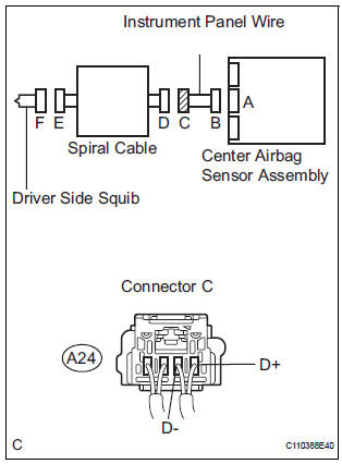
The driver side squib circuit consists of the center airbag sensor assembly, the spiral cable and the steering pad.
The circuit instructs the SRS to deploy when deployment conditions are met.
DTC B0102/11 is recorded when a short to ground is detected in the driver side squib circuit
|
DTC No. |
DTC Detecting Condition |
Trouble Area |
|
B0102/11 |
|
|
INSPECTION PROCEDURE
HINT:
- Perform the simulation method by selecting the "check mode" (signal check) with the intelligent tester (8).
- After selecting the "check mode" (signal check), perform the simulation method by wiggling each connector of the airbag system or driving the vehicle on a city or rough road
1 CHECK STEERING PAD (DRIVER SIDE SQUIB)
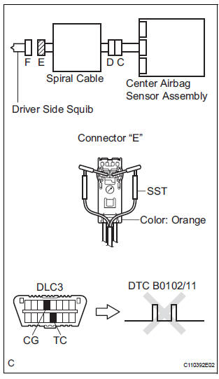
- Turn the ignition switch to the LOCK position.
- Disconnect the negative (-) terminal cable from the battery, and wait for at least 90 seconds.
- Disconnect the connectors from the steering pad.
- Connect the white wire side of SST (resistance 2.1 Ω) to the spiral cable.
CAUTION: Never connect a tester to the steering pad (driver side squib) for measurement, as this may lead to a serious injury due to airbag deployment.
NOTICE: Do not forcibly insert the SST into the terminals of the connector when connecting.
Insert the SST straight into the terminals of the connector.
SST 09843-18060
- Connect the negative (-) terminal cable to the battery, and wait for at least 2 seconds.
- Turn the ignition switch to the ON position, and wait for at least 60 seconds.
- Clear the DTCs stored in memory (5).
- Turn the ignition switch to the LOCK position.
- Turn the ignition switch to the ON position, and wait for at least 60 seconds.
- Check the DTCs (5).
OK: DTC B0102/11 is not output. HINT: Codes other than DTC B0102/11 may be output at this time, but they are not related to this check.
 Go to step 2

REPLACE STEERING PAD
2 CHECK DRIVER SIDE SQUIB CIRCUIT
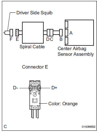
- Turn the ignition switch to the LOCK position.
- Disconnect the negative (-) terminal cable from the battery, and wait for at least 90 seconds.
- Disconnect the SST (resistance 2.1 Ω) from the spiral cable.
- Disconnect the connector from the center airbag sensor assembly.
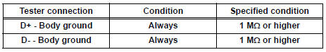
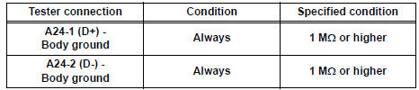
- Measure the resistance according to the value(s) in the table below.
Standard resistance
 Go to step 4

3 CHECK CENTER AIRBAG SENSOR ASSEMBLY
- Connect the connectors to the steering pad and the center airbag sensor assembly.
- Connect the negative (-) terminal cable to the battery, and wait for at least 2 seconds.
- Turn the ignition switch to the ON position, and wait for at least 60 seconds.
- Clear the DTCs stored in memory (5).
- Turn the ignition switch to the LOCK position.
- Turn the ignition switch to the ON position, and wait for at least 60 seconds.
- Check the DTCs (5).
OK: DTC B0102/11 is not output. HINT: Codes other than code B0102/11 may be output at this time, but they are not related to this check.
 REPLACE CENTER AIRBAG SENSOR
ASSEMBLY
REPLACE CENTER AIRBAG SENSOR
ASSEMBLY

USE SIMULATION METHOD TO CHECK
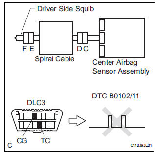
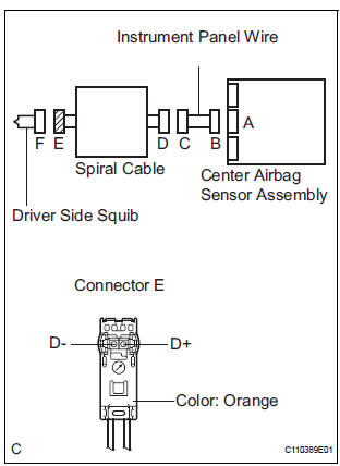
4 CHECK INSTRUMENT PANEL WIRE
- Disconnect the instrument panel wire connector from the spiral cable.
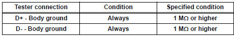
- Measure the resistance according to the value(s) in the table below.
Standard resistance
 REPAIR OR REPLACE INSTRUMENT
PANEL
WIRE
REPAIR OR REPLACE INSTRUMENT
PANEL
WIRE

5 CHECK SPIRAL CABLE
- Measure the resistance according to the value(s) in the table below.
Standard resistance
 REPLACE SPIRAL CABLE
USE SIMULATION METHOD TO CHECK
 Open in Driver Side Squib Circuit
DTC B0101/14 Open in Driver Side Squib Circuit
DESCRIPTION
The driver side squib circuit consists of the center airbag sensor assembly,
the spiral cable and the
steering pad.
The circuit instr ...
 Short to B+ in Driver Side Squib Circuit
DTC B0103/12 Short to B+ in Driver Side Squib Circuit
DESCRIPTION
The driver side squib circuit consists of the center airbag sensor assembly,
the spiral cable and the
steering pad.
The circui ...
Other materials:
Battery
Check the battery as follows:
Battery exterior
Make sure that the battery terminals are not corroded and that
there are no loose connections, cracks, or loose clamps.
Terminals
Hold-down clamp
Before recharging
When recharging, the battery produces hydrogen gas which is flammable an ...
The Other Caller cannot Hear Your Voice, or Your Voice is too Quiet or
Distorted
INSPECTION PROCEDURE
1 CHECK CELLULAR PHONE
Check if the other side can hear your voice properly.
OK:
Your voice can be heard correctly.
2 CHECK SETTINGS
Check if the mute switch is set to ON.
OK:
Mute switch is not set to ON.
3 CHECK SETTINGS
Enter the "Handsfree ...
How to proceed with
troubleshooting
HINT:
Use the following procedures to troubleshoot the cruise
control system.
*: Use the intelligent tester.
1 VEHICLE BROUGHT TO WORKSHOP
2 PROBLEM SYMPTOM CONFIRMATION
3 CHECK MULTIPLEX COMMUNICATION SYSTEM*
Refer to HOW TO PROCEED WITH TROUBLESHOOTING.
Check fo ...
