Toyota Sienna Service Manual: Open in Driver Side Squib Circuit
DTC B0101/14 Open in Driver Side Squib Circuit
DESCRIPTION
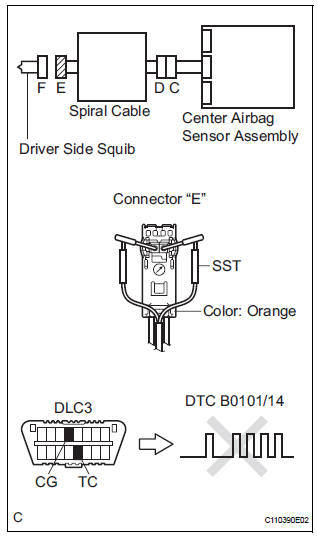
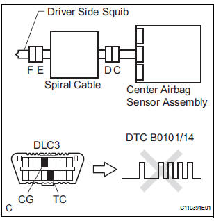
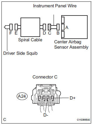
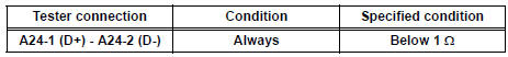
The driver side squib circuit consists of the center airbag sensor assembly, the spiral cable and the steering pad.
The circuit instructs the SRS to deploy when deployment conditions are met.
DTC B0101/14 is recorded when an open circuit is detected in the driver side squib circuit
|
DTC No. |
DTC Detecting Condition |
Trouble Area |
| B0101/14 |
|
|
INSPECTION PROCEDURE
HINT:
- Perform the simulation method by selecting the "check mode" (signal check) with the intelligent tester (8).
- After selecting the "check mode" (signal check), perform the simulation method by wiggling each connector of the airbag system or driving the vehicle on a city or rough road
1 CHECK STEERING PAD (DRIVER SIDE SQUIB)
- Turn the ignition switch to the LOCK position.
- ) Disconnect the negative (-) terminal cable from the battery, and wait for at least 90 seconds.
- ) Disconnect the connectors from the steering pad.
- Connect the white wire side of SST (resistance 2.1 Ω) to the spiral cable.
CAUTION: Never connect a tester to the steering pad (driver side squib) for measurement, as this may lead to a serious injury due to airbag deployment.
NOTICE: Do not forcibly insert the SST into the terminals of the connector when connecting.
Insert the SST straight into the terminals of the connector.
SST 09843-18060
- Connect the negative (-) terminal cable to the battery, and wait for at least 2 seconds.
- Turn the ignition switch to the ON position, and wait for at least 60 seconds.
- Clear the DTCs stored in memory (5).
- Turn the ignition switch to the LOCK position.
- Turn the ignition switch to the ON position, and wait for at least 60 seconds.
- Check the DTCs (5).
OK: DTC B0101/14 is not output.
HINT: Codes other than DTC B0101/14 may be output at this time, but they are not related to this check.
 Go to step 2

REPLACE STEERING PAD
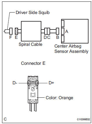
2 CHECK DRIVER SIDE SQUIB CIRCUIT
- Turn the ignition switch to the LOCK position.
- Disconnect the negative (-) terminal cable from the battery, and wait for at least 90 seconds.
- Disconnect the SST (resistance 2.1 Ω) from the spiral cable.
- ) Disconnect the connector from the center airbag sensor assembly.
- Measure the resistance according to the value(s) in the table below.
Standard resistance
 Go to step 4

3 CHECK CENTER AIRBAG SENSOR ASSEMBLY
- Connect the connectors to the steering pad and the center airbag sensor assembly.
- Connect the negative (-) terminal cabl to the battery, and wait for at least 2 seconds.
- Turn the ignition switch to the ON position, and wait for at least 60 seconds.
- Clear the DTCs stored in memory (5).
- Turn the ignition switch to the LOCK position.
- Turn the ignition switch to the ON position, and wait for at least 60 seconds.
- Check the DTCs (5).
OK: DTC B0101/14 is not output.
HINT: Codes other than code B0101/14 may be output at this time, but they are not related to this check.
 REPLACE CENTER AIRBAG SENSOR
ASSEMBLY
REPLACE CENTER AIRBAG SENSOR
ASSEMBLY

USE SIMULATION METHOD TO CHECK
4 CHECK INSTRUMENT PANEL WIRE
- Disconnect the instrument panel wire connector from the spiral cable.
- Measure the resistance according to the value(s) in the table below.
Standard resistance
 REPAIR OR REPLACE INSTRUMENT
PANEL
WIRE
REPAIR OR REPLACE INSTRUMENT
PANEL
WIRE

5 CHECK SPIRAL CABLE
- Measure the resistance according to the value(s) in the table below.
Standard resistance
 REPLACE SPIRAL CABLE

USE SIMULATION METHOD TO CHECK
 Short in Driver Side Squib Circuit
DTC B0100/13 Short in Driver Side Squib Circuit
DESCRIPTION
The driver side squib circuit consists of the center airbag sensor assembly,
the spiral cable and the
steering pad. The circuit instruc ...
 Short to GND in Driver Side Squib Circuit
DTC B0102/11 Short to GND in Driver Side Squib Circuit
DESCRIPTION
The driver side squib circuit consists of the center airbag sensor assembly,
the spiral cable and the
steering pad.
The circu ...
Other materials:
Precaution
1. Check that the battery cables are connected to the
correct terminals.
2. Disconnect the battery cables when the battery is
given a quick charge.
3. Do not perform tests with a high voltage insulation
resistance tester.
4. Never disconnect the battery cables while the engine
is runnin ...
Disassembly
1. INSPECT UNDERDRIVE PLANETARY GEAR
PRELOAD
HINT:
(See page AX-260)
2. REMOVE FRONT PLANETARY GEAR NUT
(a) Using SST, loosen the staked part of the lock nut.
SST 09930-00010 (09931-00010, 09931-00020),
09387-00050
(b) Place the underdrive planetary gear in a soft jaw
vise.
NOTIC ...
Installation
1. INSTALL SEAT MEMORY SWITCH
2. INSTALL FRONT DOOR TRIM BOARD SUBASSEMBLY
LH
3. INSTALL POWER WINDOW REGULATOR MASTER
SWITCH ASSEMBLY
4. INSTALL FRONT DOOR INSIDE HANDLE BEZEL
PLUG LH
5. INSTALL FRONT DOOR LOWER FRAME BRACKET GARNISH LH
Engage the 4 claws to install the seat me ...
