Toyota Sienna Service Manual: Inspection
1. INSPECT INVERTER MAIN SWITCH
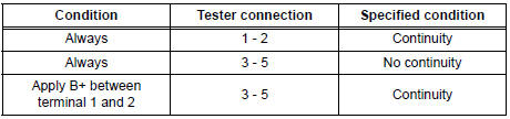
- Inspect the continuity between terminal at the each switch position shown in the chart.
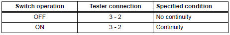
If continuity is not as specified, replace the main switch assembly.
- Inspect the bulb state when connecting the battery to each terminal
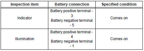
If operation is not as specified, check the faulty bulb.
- Inspect continuity of the bulb by connecting the
tester as shown in the illustration.
If continuity exists, replace the main switch assembly.
If no continuity exists, replace the bulb.
2. INSPECT INVERTER RELAY
- Inspect continuity between terminal at the each switch position shown in the chart.
If continuity is not as specified, replace the point socket relay.
Installation
1. INSTALL VOLTAGE INVERTER ASSEMBLY
- Install the voltage inverter assembly with the 2 bolts.
Torque: 5.4 N*m (55 kgf*cm, 47 in.*lbf)
NOTICE: Tighten the bolts in order shown in the illustration to in the voltage inverter assembly.
2. INSTALL QUARTER TRIM FRONT PANEL ASSEMBLY LH
3. INSTALL BACK DOOR SCUFF PLATE
4. INSTALL BACK DOOR WEATHERSTRIP
5. INSTALL REAR DOOR WEATHERSTRIP LH
6. INSTALL REAR DOOR SCUFF PLATE LH
 Removal
1. REMOVE REAR DOOR SCUFF PLATE LH
2. REMOVE REAR DOOR WEATHERSTRIP LH
3. REMOVE BACK DOOR WEATHERSTRIP
4. REMOVE BACK DOOR SCUFF PLATE
5. REMOVE QUARTER TRIM FRONT PANEL ASSEMBLY LH
6. REMOVE VO ...
 Video terminal
COMPONENTS
REMOVAL
1. REMOVE REAR DOOR SCUFF PLATE LH
2. REMOVE REAR DOOR WEATHERSTRIP LH
3. REMOVE BACK DOOR WEATHERSTRIP
4. REMOVE BACK DOOR SCUFF PLATE
5. REMOVE QUARTER TRIM FRONT PANE ...
Other materials:
Evaporative Emission Control System Incorrect
Purge Flow
DTC P0441 Evaporative Emission Control System Incorrect
Purge Flow
DTC SUMMARY
DESCRIPTION
The circuit description can be found in the EVAP (Evaporative Emission)
System.
INSPECTION PROCEDURE
Refer to the EVAP System.
MONITOR DESCRIPTION
The two monitors, Key-Off and Purge Flow, are us ...
Disassembly
1. REMOVE STOP LIGHT SWITCH ASSEMBLY
(a) Turn the stop light switch assembly
counterclockwise and remove the stop light switch
assembly.
(b) Remove the stop light switch mounting adjuster
from the brake pedal support sub-assembly.
2. REMOVE STOP LIGHT SWITCH CUSHION
(a) Remove the stop ligh ...
Removal
1. DISCONNECT CABLE FROM NEGATIVE BATTERY
TERMINAL
2. REMOVE V-BANK COVER SUB-ASSEMBLY (See
page EM-28)
3. REMOVE PURGE VSV
(a) Disconnect the purge VSV connector.
(b) Disconnect the 2 purge line hoses from the purge
VSV.
(c) Remove the purge VSV from the air cleaner hose.
(d) R ...
