Toyota Sienna Service Manual: Steering Angle Sensor Communication Stop Mode
DESCRIPTION
|
Detection Item |
Symptom |
Trouble Area |
| Steering Angle Sensor Communication Stop Mode |
|
|
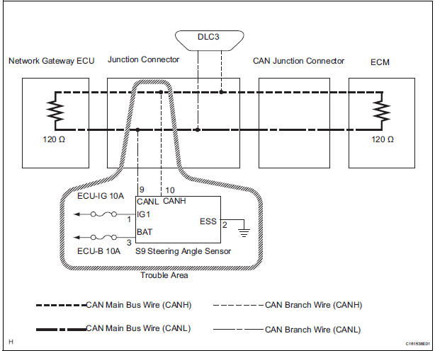
WIRING DIAGRAM
INSPECTION PROCEDURE
NOTICE:
- Turn the ignition switch off before measuring the resistances of CAN bus main wires and CAN bus branch wires.
- After the ignition switch is turned off, check that the key reminder warning system and light reminder warning system are not in operation.
- Before measuring the resistance, leave the vehicle as is for at least 1 minute and do not operate the ignition switch, any other switches, or the doors. If any doors need to be opened in order to check connectors, open the doors and leave them open.
HINT: Operating the ignition switch, any switches, or any doors triggers related ECU and sensor communication with the CAN. This communication will cause the resistance value to change.
1 CHECK OPEN IN CAN BUS WIRE (STEERING ANGLE SENSOR BRANCH WIRE)
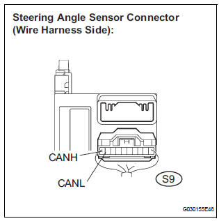
- Turn the ignition switch off.
- Disconnect the steering angle sensor connector.
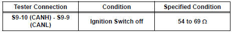
- Measure the resistance according to the value(s) in the table below.
Standard resistance
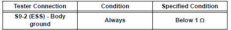
2 CHECK WIRE HARNESS (BAT, IG1, ESS)
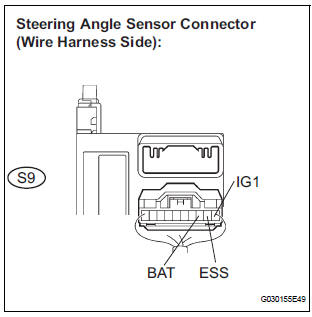
- Measure the resistance according to the value(s) in the table below.
Standard resistance
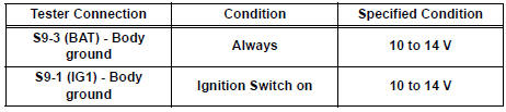
- Measure the voltage according to the value(s) in the table below.
Standard voltage
REPLACE STEERING ANGLE SENSOR
 Gateway ECU Communication Stop Mode
DESCRIPTION
Detection Item
Symptom
Trouble Area
Gateway ECU
Communication Stop
Mode
"Gateway" is not displayed on the "Communication ...
 Yaw Rate Sensor Communication Stop Mode
DESCRIPTION
Detection Item
Symptom
Trouble Area
Yaw Rate Sensor
Communication Stop
Mode
"Yaw rate/ Deceleration sensor" is not displayed ...
Other materials:
Diagnosis system
1. CHECK DLC3
The vehicle's ECU uses ISO 15765-4 for
communication protocol. The terminal arrangement
of the DLC3 complies with SAE J1962 and matches
the ISO 15765-4 format.
NOTICE:
*: Before measuring the resistance, leave the
vehicle as is for at least 1 minute and do ...
The Other Caller cannot Hear Your Voice, or Your Voice is too Quiet or
Distorted
INSPECTION PROCEDURE
1 CHECK CELLULAR PHONE
Check if the other side can hear your voice properly.
OK:
Your voice can be heard correctly.
2 CHECK SETTINGS
Check if the mute switch is set to ON.
OK:
Mute switch is not set to ON.
3 CHECK SETTINGS
Enter the "Handsfree ...
Open in One Side of CAN Branch Line
DESCRIPTION
If 2 or more ECUs and/or sensors do not appear on the intelligent tester
"Communication Bus Check"
screen, one side of the CAN branch wire may be open. (One side of the CAN-H
[branch wire] / CAN-L
[branch wire] of the ECU and/or sensor is open.)
Symptom
...
