Toyota Sienna Service Manual: Rear speaker
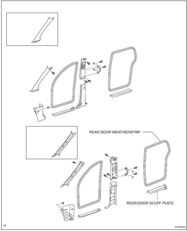
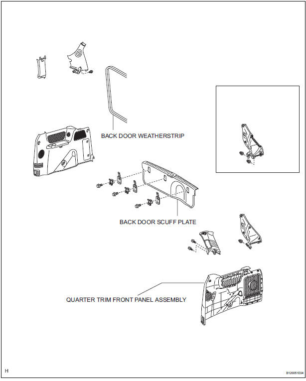
COMPONENTS
ON-VEHICLE INSPECTION
1. INSPECT REAR SPEAKER
HINT: Remove interior parts so that the rear speaker can be seen.
- Check the speaker installation.
OK: The speaker is securely installed.
If the result is not as specified, reinstall the rear speaker.
- Visually check the speaker.
OK: The cone paper of the speaker is not torn.
If the result is not as specified, replace the rear speaker.
- Speaker resistance check
- Disconnect the rear speaker connector.
- Measure the resistance between the terminals of the speaker.
Standard resistance:
6 Speaker system:
Approximately 4 Ω
10 Speaker system:
Approximately 2.4 Ω
If the result is not as specified, replace the rear speaker.
REMOVAL
1. REMOVE REAR DOOR SCUFF PLATE
2. REMOVE REAR DOOR WEATHERSTRIP
3. REMOVE BACK DOOR WEATHERSTRIP
4. REMOVE BACK DOOR SCUFF PLATE
5. REMOVE QUARTER TRIM FRONT PANEL ASSEMBLY
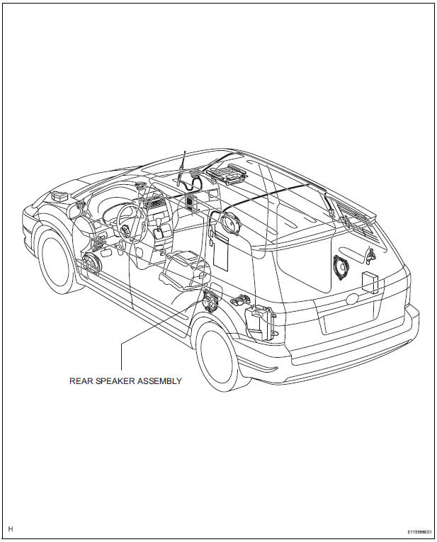
6. REMOVE REAR SPEAKER ASSEMBLY
- Disconnect the connector.
- Remove the 3 screws and the rear speaker assembly
INSTALLATION
1. INSTALL REAR SPEAKER ASSEMBLY
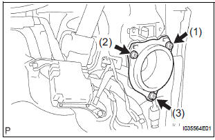
- Install the rear speaker assembly with the 3 screws.
NOTICE: Tighten the screws in order shown in the illustration to install the rear speaker assembly.
- Connect the connector.
2. INSTALL QUARTER TRIM FRONT PANEL ASSEMBLY
3. INSTALL BACK DOOR SCUFF PLATE
4. INSTALL BACK DOOR WEATHERSTRIP
5. INSTALL REAR DOOR WEATHERSTRIP
6. INSTALL REAR DOOR SCUFF PLATE
 Stereo component speaker
COMPONENTS
ON-VEHICLE INSPECTION
1. INSPECT STEREO COMPONENT SPEAKER
HINT:
Remove interior parts so that the stereo component
speaker can be seen.
Check the speaker installation.
...
 No. 1 Speaker with box
COMPONENTS
ON-VEHICLE INSPECTION
1. INSPECT NO.1 SPEAKER WITH BOX
HINT:
Remove interior parts so that the No.1 speaker with box
can be seen.
Check the speaker installation.
OK ...
Other materials:
Front stabilizer bar (for 4wd)
COMPONENTS
...
Symptom simulation
HINT:
The most difficult case in troubleshooting is when no
problem symptoms occur. In such a case, a thorough
problem analysis must be carried out. A simulation of the
same or similar conditions and environment in which the
problem occurred in the customer's vehicle should be
carried out. No ...
Short in Curtain Shield Squib RH Circuit
DTC B1160/83 Short in Curtain Shield Squib RH Circuit
DESCRIPTION
The curtain shield squib RH circuit consists of the center airbag sensor
assembly and the curtain shield
airbag assembly RH.
The circuit instructs the SRS to deploy when deployment conditions are met.
DTC B1160/83 is record ...
