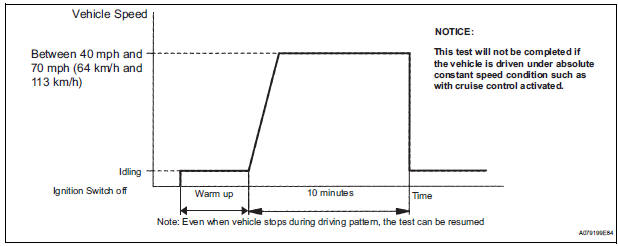
Toyota Sienna Service Manual: Catalyst monitor (active air-fuel ratio control type)

(a) Preconditions
The monitor will not run unless:
- The MIL is OFF.
(b) Drive Pattern
(1) Connect an intelligent tester.
(2) Turn the ignition switch to the ON position.
(3) Turn the tester or scan tool ON.
(4) Clear the DTCs.
(5) Start the engine and warm it up.
(6) Drive the vehicle at between 40 mph and 70 mph (64 km/h and 113 km/h) for at least 10 minutes.
(c) Monitor Status
(1) Check the Readiness Monitor status displayed on the tester.
(2) If the status does not switch to COMPL (complete), extend the driving time.
 Purpose of readiness tests
The On-Board Diagnostic (OBD II) system is
designed to monitor the performance of emissionrelated
components, and indicate any detected
abnormalities with DTCs (Diagnostic Trouble Codes).
...
 Evap monitor (key-off type)
(a) Preconditions
The monitor will not run unless:
The fuel tank is less than 90% full.
The altitude is less than 8000 ft (2450 m).
The vehicle is stationary.
The engine coolant temperature ...
Other materials:
Bluetooth tel check mode
HINT:
Illustration may differ from the actual vehicle depending on
the device settings and options. Therefore, some detailed
area may not be shown exactly the same as on the actual
vehicle.
1. ENTER DIAGNOSTIC MODE
2. BLUETOOTH TEL CHECK
Select "Bluetooth TEL Check" fro ...
Speed sensor check (when using sst check wire)
(a) Check the speed sensor signal.
(1) Drive the vehicle straight forward. Drive the
vehicle at a speed of 45 km/h (28 mph) or higher
for several seconds and check that the ABS
warning light goes off.
HINT:
The signal check may not be completed if the
vehicle has its wheels spun or the stee ...
Disposal
1. DISPOSE OF FRONT SEAT OUTER BELT ASSEMBLY (WHEN INSTALLED IN VEHICLE)
NOTICE:
Never dispose of a front seat outer belt assembly
with an deactivated pretensioner.
The seat belt pretensioner produces an exploding
sound when it activates, so perform the operation
outdoors wh ...
