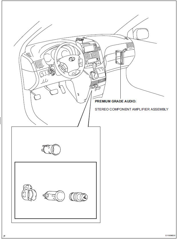
Toyota Sienna Service Manual: Stereo component amplifier
COMPONENTS
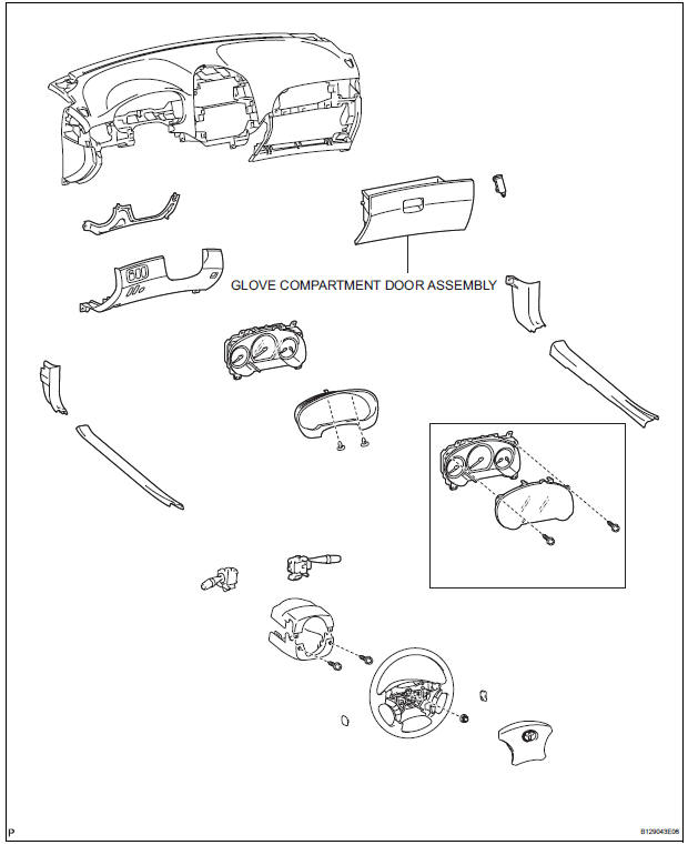
Removal
1. REMOVE GLOVE COMPARTMENT DOOR ASSEMBLY
2. REMOVE STEREO COMPONENT AMPLIFIER ASSEMBLY
- Disconnect the connectors.
- Remove the 2 nuts and the stereo component amplifier assembly.
Installation
1. INSTALL STEREO COMPONENT AMPLIFIER ASSEMBLY
- Install the stereo component amplifier assembly with the 2 nuts.
- Connect the connectors.
2. INSTALL GLOVE COMPARTMENT DOOR ASSEMBLY
 Installation
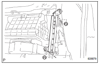
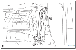
1. INSTALL RADIO NO. 2 BRACKET
Install radio No. 2 bracket with the 4 screws.
2. INSTALL RADIO NO. 1 BRACKET
Install radio No. 1 bracket with the 4 screws.
3. INSTALL R ...
 Television display
COMPONENTS
Removal
1. REMOVE TELEVISION BASE
Release the 4 clips and remove the television base.
2. REMOVE TELEVISION DISPLAY ASSEMBLY
Disconnect the connector and r ...
Other materials:
Child restraint systems with a top tether strap (third seat)
Center seat
Secure the child restraint
system using the seat belt or
LATCH anchors. Adjust the
head restraint to the uppermost
position.
Latch the hook onto the
anchor bracket and tighten
the top tether strap.
Make sure the top tether strap is
securely latched.
...
On-vehicle inspection
1. INSPECT STEERING PAD (VEHICLE NOT INVOLVED IN COLLISION)
Perform a diagnostic system check.
With the steering pad installed on the vehicle,
perform a visual check. If there are any defects as
mentioned below, replace the steering pad with a
new one:
Cuts, minute cracks or marked ...
Data list / active test
1. DATA LIST
The wireless door lock control data list can be
displayed while the intelligent tester is connected to
the DLC3 with the ignition switch in the ON position.
Follow the prompts on the tester screen to access
the DATA LIST.
BODY:
2. ACTIVE TEST
HINT:
Performing the ACT ...
