Toyota Sienna Service Manual: No Master/ Connection Check Error
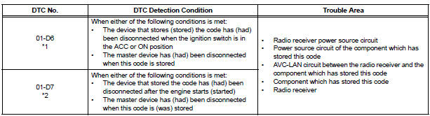
DTC 01-D6 No Master
DTC 01-D7 Connection Check Error
DESCRIPTION
HINT:
- *1: Even if no fault is present, this trouble code may be stored depending on the battery condition or engine start voltage.
- *2: When 210 seconds have elapsed after disconnecting the power supply connector of the master component with the ignition switch in the ACC or ON position, this code is stored.
NOTICE:
- Before starting troubleshooting, be sure to clear DTCs to erase codes stored due to the reasons described in the HINT above. Then, check for DTCs and troubleshoot according to the output DTCs.
- The radio receiver is the master unit.
- Be sure to clear and recheck DTCs after the inspection is completed to confirm that no DTCs are output.
INSPECTION PROCEDURE
NOTICE: Be sure to read DESCRIPTION before performing the following procedures.
1 CHECK RADIO RECEIVER POWER SOURCE CIRCUIT
Refer to the radio receiver power source circuit.
If the power source circuit is operating normally, proceed to the next step.
2 IDENTIFY THE COMPONENT WHICH HAS STORED THIS CODE
- Enter the diagnostic mode
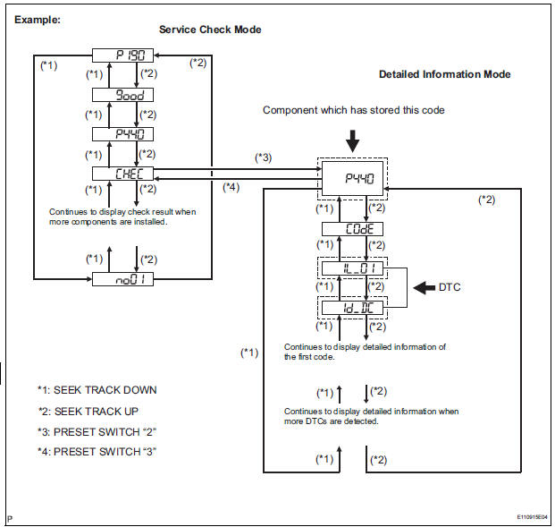
- Press the preset switch "3" to change to "Detailed Information Mode".
- Identify the component which has stored this code.
Component Table:

HINT:
- "440 (stereo component amplifier)" is the component which has stored this code in the example shown in the illustration.
- For details of the DTC display, refer to "DTC CHECK/ CLEAR"
3 CHECK POWER SOURCE CIRCUIT OF COMPONENT WHICH HAS STORED THIS CODE
- Inspect the power source circuit of the component which
has stored this code.
If the power source circuit is operating normally, proceed to the next step
Component Table:

4 INSPECT RADIO RECEIVER
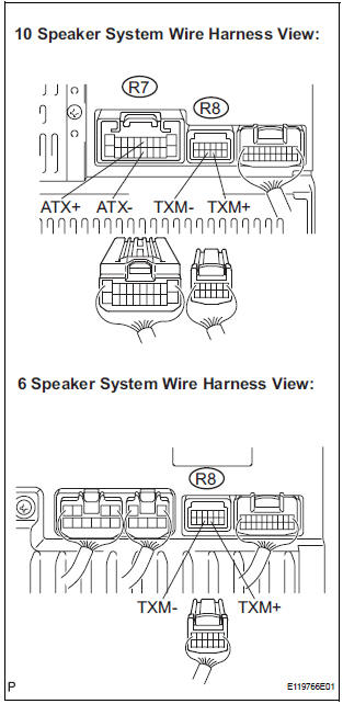
- Disconnect the radio receiver connectors.
- Measure the resistance according to the value(s) in the table below.
Standard resistance
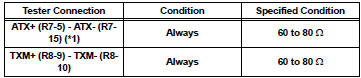
*1: 10 Speaker System
5 CHECK HARNESS AND CONNECTOR (RADIO RECEIVER - COMPONENT WHICH HAS STORED THIS CODE)
HINT: For details of the connectors, refer to the "TERMINALS OF ECU".
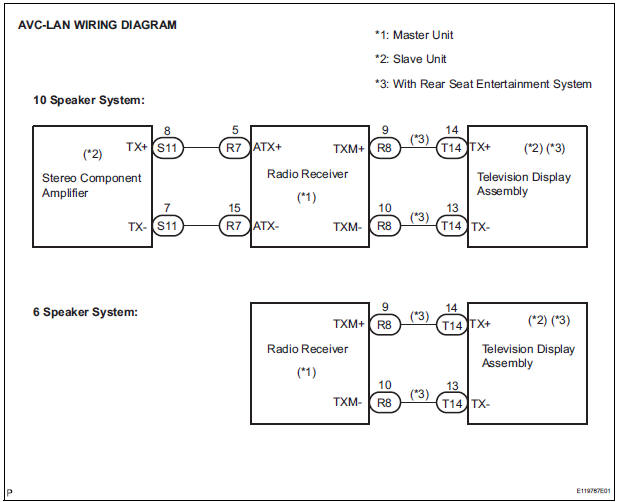
- Referring to the AVC-LAN wiring diagram below, check the AVC-LAN circuit between the radio receiver and the component which has stored this code.
- Disconnect all connectors between the radio receiver and the component which has stored this code.
- Check for an open or short in the AVC-LAN circuit between the radio receiver and the component which has stored this code.
OK: There is no open or short circuit.
6 REPLACE COMPONENT WHICH HAS STORED THIS CODE
- Replace the component which has stored this code with a normal one and check if the same problem occurs again.
OK: Same problem does not occur
END
 Absence of Registration Unit/ No Response for Connection Check/ Last Mode
Error/ No Response Against ON / OFF Command/ Mode Status Error/ Slave Reset
Absence of Registration Unit/ No Response for Connection Check/ Last Mode
Error/ No Response Against ON / OFF Command/ Mode Status Error/ Slave Reset
DESCRIPTION
HINT:
*1: Even if no fault is present, this trouble code may be stored
depending on the battery condition or
engine start voltage.
*2: If the power connector is ...
 Transmission Error
DTC 01-DC Transmission Error
DESCRIPTION
HINT:
*1: This code may be stored if the engine is started, idled for 60 seconds and
then started again.
NOTICE:
Before starting troubl ...
Other materials:
Short to B+ in Curtain Shield Squib RH Circuit
DTC B1163/82 Short to B+ in Curtain Shield Squib RH Circuit
DESCRIPTION
The curtain shield squib RH circuit consists of the center airbag sensor
assembly and the curtain shield
airbag assembly RH.
The circuit instructs the SRS to deploy when deployment conditions are met.
DTC B1163/82 is ...
Power Source Circuit
DESCRIPTION
This is the power source circuit for the outer mirror control ECU.
WIRING DIAGRAM
INSPECTION PROCEDURE
1 INSPECT OUTER MIRROR CONTROL ECU (POWER SOURCE)
Disconnect the O9 or O11 ECU connector.
Measure the voltage and resistance according to the
value(s) in the t ...
Poor Sound Quality in All Modes (Low Volume)
INSPECTION PROCEDURE
1 CHECK AUDIO SETTINGS
Set "BASS", "MID", and "TREB" to the initial values and
check that sound is normal.
OK:
Malfunction disappears.
2 COMPARE WITH ANOTHER VEHICLE OF SAME MODEL
Compare with another vehicle of the same model.
...
