
Toyota Sienna Service Manual: On-vehicle inspection
1. FRONT SEAT SIDE AIRBAG ASSEMBLY (VEHICLE NOT INVOLVED IN COLLISION)
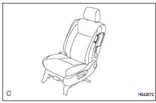
- Perform a diagnostic system check.
- With the front seat side airbag assembly installed on the vehicle, perform a visual check. If there are any defects as mentioned below, replace the front seatback assembly with a new one: Cuts, minute cracks or marked discoloration on the front seatback assembly around the front seat side airbag assembly
2. FRONT SEAT SIDE AIRBAG ASSEMBLY (VEHICLE INVOLVED IN COLLISION AND AIRBAG HAS NOT DEPLOYED)
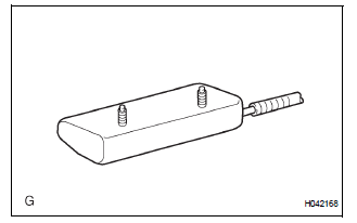
- Perform a diagnostic system check.
- With the front seat side airbag assembly removed from the vehicle, perform a visual check. If there are any defects as mentioned below, replace the front seat side airbag assembly with a new one:
- Cuts, minute cracks or marked discoloration on the front seat side airbag assembly.
- Cracks or other damage to the wire harness or connector.
CAUTION: Be sure to follow the correct removal and installation procedures.

 Disposal
HINT:
Use the same procedures for the RH side and LH side.
The procedures listed below are for the LH side.
When scrapping a vehicle equipped with the SRS or
disposing of t ...
Other materials:
Display does not Dim when Light Control Switch is Turned ON
INSPECTION PROCEDURE
1 CHECK IMAGE QUALITY SETTING
Enter the display adjustment screen by pressing the
"DISPLAY" switch.
Turn the light control switch to the TAIL position.
Check if "DAY MODE" on the display adjustment is ON.
OK:
"DAY MODE" ...
Display Signal Circuit between Radio and Navigation Assembly and
Television Camera Assembly
DESCRIPTION
This is the display signal circuit of the television camera assembly.
WIRING DIAGRAM
INSPECTION PROCEDURE
1 CHECK HARNESS AND CONNECTOR (RADIO AND NAVIGATION ASSEMBLY - TELEVISION
CAMERA ASSEMBLY)
Disconnect the R10 connector from the radio and
navigation assembly.
&nbs ...
Throttle / Pedal Position Sensor / Switch "A" Circuit Range / Performance
Problem
HINT:
This DTC relates to the Throttle Position (TP) sensor.
DESCRIPTION
Refer to DTC P0120 (See page ES-145).
MONITOR DESCRIPTION
The ECM uses the TP sensor to monitor the throttle valve opening angle.
This sensor transmits two signals: VTA1 and VTA2. VTA1 is used to detect the
th ...
