
Toyota Sienna Service Manual: Installation
1. INSTALL SPIRAL CABLE
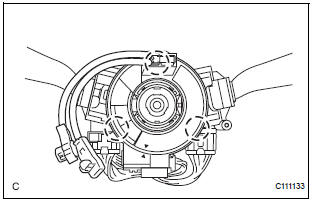
- Check that the front wheels are facing straight ahead.
- Set the turn signal switch to the neutral position.
NOTICE: If it is not in the neutral position, the pin of the turn signal switch may snap.
- Install the spiral cable.
NOTICE: When replacing the spiral cable with a new one, remove the lock pin before installing the steering wheel assembly.
- Connect the connectors to the spiral cable.
NOTICE: When handling the airbag connector, take care not to damage the airbag wire harness.
2. INSTALL STEERING COLUMN COVER
- Install the steering column cover with the 2 screws.
3. ADJUST SPIRAL CABLE
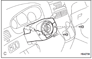
- Check that the ignition switch is off.
- Check that the battery negative (-) terminal is disconnected.
CAUTION: After removing the terminal, wait for at least 90 seconds before starting the operation.
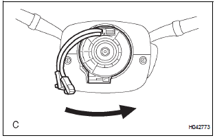
- Rotate the spiral cable counterclockwise slowly by hand until it feels firm.
NOTICE: Do not turn the spiral cable by the airbag wire harness.
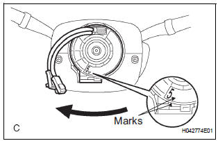
- Rotate the spiral cable clockwise approximately 2.5 turns to align the marks.
NOTICE: Do not turn the spiral cable by the airbag wire harness.
HINT: The spiral cable will rotate approximately 2.5 turns to both the left and right from the center.
4. INSTALL STEERING WHEEL ASSEMBLY
5. INSPECT STEERING WHEEL CENTER POINT
6. INSTALL STEERING PAD
7. INSTALL STEERING WHEEL NO.2 COVER LOWER
8. INSTALL STEERING WHEEL NO.3 COVER LOWER
9. CONNECT CABLE TO NEGATIVE BATTERY TERMINAL
10. INSPECT STEERING PAD
11. PERFORM INITIALIZATION
- Perform initialization.
HINT: Some systems need initialization when disconnecting the cable from the negative battery terminal.
12. INSPECT SRS WARNING LIGHT
- Inspect the SRS warning light
 Removal
1. PRECAUTION
CAUTION:
Be sure to read "PRECAUTION" thoroughly before
servicing.
2. DISCONNECT CABLE FROM NEGATIVE BATTERY
TERMINAL
CAUTION:
Wait for 90 seconds after disconnecting th ...
 Front passenger airbag assembly
COMPONENTS
...
Other materials:
Dtc clear
(A) when using the obd ii scan tool or intelligent
tester: clearing the dtcs.
(1) Connect the intelligent tester together with the
CAN VIM (controller area network vehicle
interface module) to the DLC3.
(2) Turn the ignition switch to the ON position and
turn the OBD II scan tool or the inte ...
Disassembly
1. REMOVE LOWER BALL JOINT ASSEMBLY FRONT LH
(a) Remove the cotter pin and nut.
(b) Using SST(s), remove the lower ball joint assembly
front LH.
SST 09628-62011
2. REMOVE FRONT WHEEL BEARING DUST DEFLECTOR NO.1 LH
(a) Using a screwdriver, remove the bearing dust
deflector NO. 1 LH ...
Removal
1. PRECAUTION
CAUTION: Be sure to read "PRECAUTION" thoroughly before
servicing.
2. DISCONNECT CABLE FROM NEGATIVE BATTERY
TERMINAL
CAUTION:
Wait for 90 seconds after disconnecting the cable to
prevent the airbag working.
3. REMOVE FRONT SEAT ASSEMBLY (for Manual Seat)
4. REMOVE ...
