Toyota Sienna Service Manual: TC and CG Terminal Circuit
DESCRIPTION
Connecting terminals TC and CG of the DLC3 causes the ECU to display the DTC by blinking the ABS warning light and/or VSC warning light.
WIRING DIAGRAM
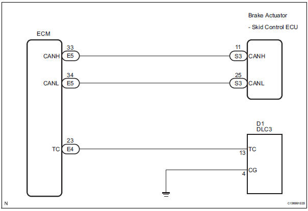
INSPECTION PROCEDURE
NOTICE: When replacing the brake actuator assembly, perform zero point calibration (See page BC-70).
1 CHECK CAN COMMUNICATION SYSTEM
(a) Check if the CAN communication system DTC is output (See page BC-82).
Result

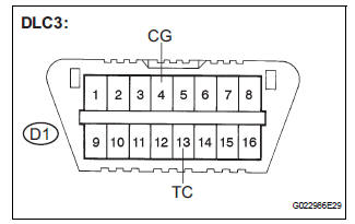
2 INSPECT DLC3
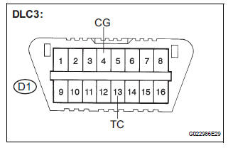
(a) Turn the ignition switch to the ON position.
(b) Measure the voltage according to the value(s) in the table below.
Standard voltage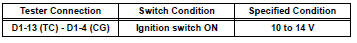
Result 


3 CHECK HARNESS AND CONNECTOR (TC of DLC3 - ECM)
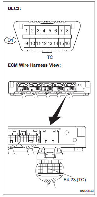
(a) Turn the ignition switch off.
(b) Disconnect the ECM connector.
(c) Measure the resistance according to the value(s) in the table below.
Standard resistance 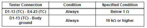

4 CHECK HARNESS AND CONNECTOR (CG of DLC3 - BODY GROUND)
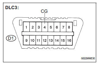
(a) Measure the resistance according to the value(s) in the table below.
Standard resistance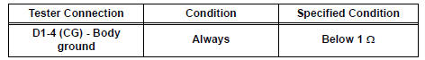

5 CHECK ECM (TC of DLC3 INPUT)
(a) Reconnect the ECM connector.
(b) Using SST, connect terminals TC and CG of the DLC3.
SST 09843-18040
(c) Turn the ignition switch to the ON position.
(d) Check that the check engine warning light is blinking.
Result 
HINT: If troubleshooting has been carried out according to the Problem Symptoms Table, refer back to the table and proceed to the next step before replacing the part (See page BC-79).

REPLACE BRAKE ACTUATOR ASSEMBLY
 Skid Control Buzzer Circuit
DESCRIPTION
The skid control buzzer sounds and SLIP indicator blinking during VSC
operation.
WIRING DIAGRAM
INSPECTION PROCEDURE
1 PERFORM ACTIVE TEST USING INTELLIGENT TESTER (SKID CONTROL ...
 TS and CG Terminal Circuit
DESCRIPTION
In the sensor check mode, a malfunction of the speed sensor that cannot be
detected when the vehicle is
stopped is detected while driving.
Transition to the sensor check mode can be ...
Other materials:
Voice settings
This screen is used for guidance for voice command systems
setting.
Adjust the voice guidance volume
setting.
Set the voice recognition
prompts “High”, “Low” or “Off”.
Set the train voice recognition.
Set the voice prompt interrupt
on/off.
Set the voice recognition ...
Gauges and meters
The displayed content may differ depending on the type of meter.
Vehicles with monochrome display
Vehicles with color display
Tachometer
Displays the engine speed in revolutions per minute
Multi-information display
Presents the driver with a variety of driving-related d ...
Dtc check / clear
1. DTC CHECK/CLEAR (WHEN USING INTELLIGENT TESTER):
(a) DTC check
(1) Connect the intelligent tester to the DLC3.
(2) Turn the ignition switch to the ON position.
(3) Read the DTCs following the prompts on the
tester screen.
(b) DTC clear
(1) Connect the intelligent tester to the DLC3 ...
