Toyota Sienna Service Manual: Vehicle stability control system
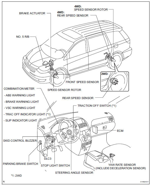
Parts location
- System description
- How to proceed with troubleshooting
- Calibration
- Test mode procedure
- Terminals of ecu
- Dtc check / clear
- Freeze frame data
- Data list / active test
- Diagnostic trouble code chart
- Problem symptoms table
 TS and CG Terminal Circuit
DESCRIPTION
The Test Mode (signal check) circuit detects trouble in the sensor or switch
signal, which cannot be
detected by the DTC check.
Connecting terminals TS and CG of the DLC3 starts the ...
 System description
1. SYSTEM DESCRIPTION
(a) ABS
(Anti-lock Brake System)
The ABS helps prevent wheels from locking when
the brake is applied firmly or when braking on a
slippery surface.
(b) EBD
(Electronic Brak ...
Other materials:
Diagnostic trouble code chart
If a trouble code is displayed during the DTCs check (sensor
check), check the circuit listed for the code in the table below
(Proceed to the page given for that circuit).
AIR CONDITIONING SYSTEM
HINT:
*1: If the cabin temperature is approximately -18.6°C (-
3.7°F) or lo ...
Door control switch
INSPECTION
1. INSPECT DOOR CONTROL SWITCH ASSEMBLY
Measure the resistance according to the value(s) in
the table below.
Standard resistance
HINT:
If the result is not as specified, replace the switch. ...
Problem symptoms table
HINT:
Before inspecting the suspected areas listed in the table
below, check the fuse and relay.
Before inspecting the suspected areas listed in the table
below, check for DTCs.
Methods used to verify the cause of the problem are listed
in order of probability in the ...
