Toyota Sienna Service Manual: TS and CG Terminal Circuit
DESCRIPTION
In the sensor check mode, a malfunction of the speed sensor that cannot be detected when the vehicle is stopped is detected while driving.
Transition to the sensor check mode can be performed by connecting terminals TS and CG of the DLC3 and turning the ignition switch from off to the ON position.
WIRING DIAGRAM
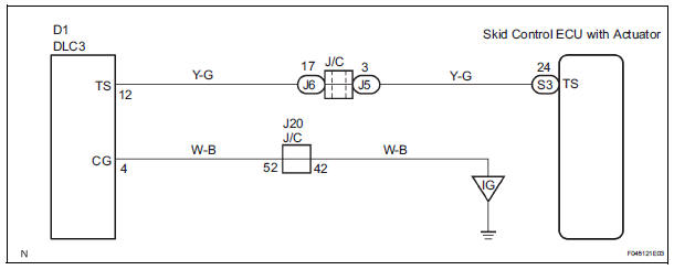
INSPECTION PROCEDURE
1 INSPECT DLC3
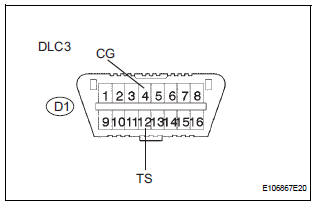
(a) Turn the ignition switch to the ON position.
(b) Measure the voltage according to the value(s) in the table below.
Standard voltage

2 CHECK HARNESS AND CONNECTOR (TS of DLC3 - SKID CONTROL ECU)
(a) Disconnect the skid control ECU connector.
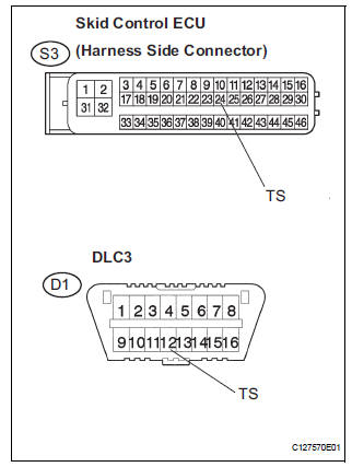
(b) Measure the resistance according to the value(s) in the table below.
Standard resistance 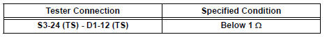
(c) Measure the resistance according to the value(s) in the table below.
Standard resistance 
NOTICE: When replacing the brake actuator assembly, perform zero point calibration (See page BC-70).

REPLACE BRAKE ACTUATOR ASSEMBLY
 TC and CG Terminal Circuit
DESCRIPTION
Connecting terminals TC and CG of the DLC3 causes the ECU to display the DTC
by blinking the ABS
warning light and/or VSC warning light.
WIRING DIAGRAM
INSPECTION PROCEDURE
NOTI ...
 Brake actuator (w/ vsc)
Components
...
Other materials:
Open in Stop Light Switch Circuit
DTC C1249/49 Open in Stop Light Switch Circuit
DESCRIPTION
WIRING DIAGRAM
INSPECTION PROCEDURE
1 CHECK STOP LIGHT SWITCH OPERATION
(a) Check that the stop light comes on when the brake pedal
is depressed and goes off when the brake pedal is
released.
OK
HINT:
Check the stop li ...
Terminals of ECM
1. SFI SYSTEM
HINT:
The standard normal voltage between each pair of the
ECM terminals is shown in the table below. The
appropriate conditions for checking each pair of the
terminals are also indicated.
The check results should be compared with the standard
normal voltage for that pair of ...
Power Window cannot be Operated by Wireless Operation
DESCRIPTION
When the switch on the transmitter is operated during normal operating
conditions, the
multiplex network body ECU sends a request signal to the master switch and the
regulator switches which
then drive the applicable power window motors.
INSPECTION PROCEDURE
1 CHECK WIRELESS DOO ...
