Toyota Sienna Service Manual: Terminals of ECU
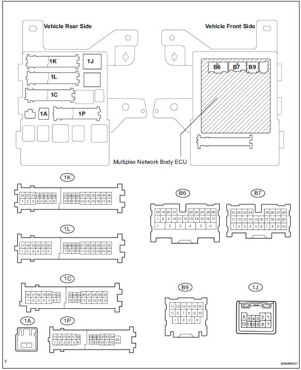
1. CHECK DRIVER SIDE J/B ASSEMBLY (MULTIPLEX NETWORK BODY ECU)
- Disconnect the 1C, 1J, 1L, 1K, 1P, B6, B7 and B9 J/ B connectors.
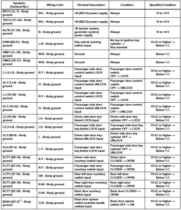
- Measure the voltage and resistance according to the value(s) in the table below.
Standard
HINT:
- If the result is not as specified, there may be a malfunction on the wire harness side.
- *1: w/o Power back door
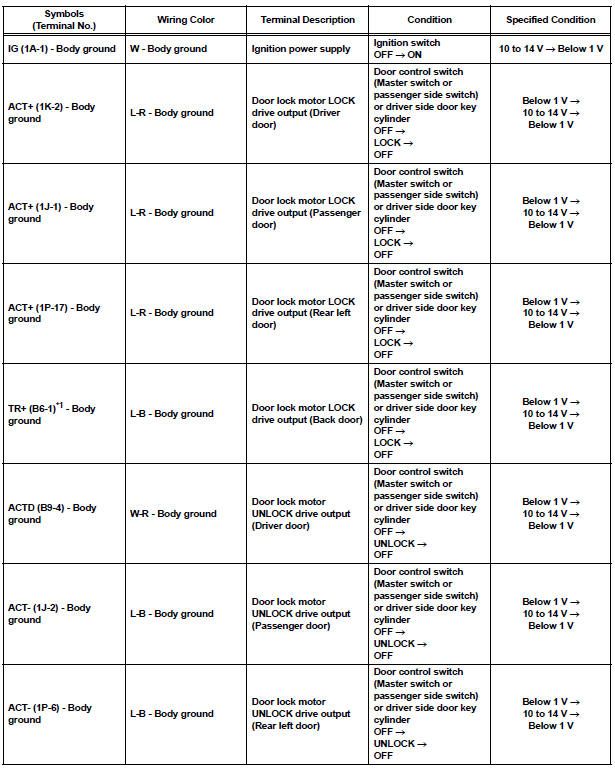
- Reconnect the J/B and ECU connectors and measure the voltage according to the value(s) in the table below.
Standard voltage
HINT:
- *1: w/o Power Back Door
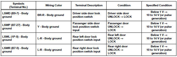
- Use an oscilloscope to check the output voltages of terminals LSWD, LSWP, LSWL and LSWR.
- If the result is not as specified, the J/B (body ECU) may have a malfunction.
2. CHECK POWER BACK DOOR ECU (w/ Power back door system)
- Disconnect the P13 and P14 ECU connectors.
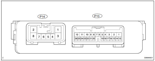
- Measure the voltage and resistance according to the value(s) in the table below.
Standard
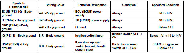
HINT: If the result is not as specified, there may be a malfunction on the wire harness side.
- Reconnect the ECU connectors and measure the voltage according to the value(s) in the table below.
Standard voltage
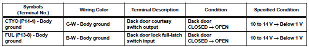
HINT: If the result is not as specified, the ECU may have a malfunction.
 Problem symptoms table
HINT:
Inspect the fuse and relay before investigating the suspected
areas shown in the table below.
POWER DOOR LOCK CONTROL SYSTEM
...
 Diagnosis system
1. CHECK DLC3
The vehicle's ECU uses ISO 15765-4 for
communication protocol. The terminal arrangement
of the DLC3 complies with SAE J1962 and matches
the ISO 15765-4 format.
...
Other materials:
Black Screen
INSPECTION PROCEDURE
1 CHECK DISPLAY SETTING
Check that the display is not in "Screen OFF" mode.
OK:
The display setting is not in "Screen OFF" mode.
2 CHECK IMAGE QUALITY SETTING
Check that the screen color quality can be set.
OK:
Setting is possible.
PRESS PA ...
Problem symptoms table
POWER BACK DOOR SYSTEM
Symptom
Suspected Area
Power back door does not operate when switch* is
pressed (* Switch indicates the satellite switch for
power back door)
ECU-B fuse
Power back door main switch
Satellite switch
Power back door tou ...
Transmission Range Sensor Circuit Malfunction
(PRNDL Input)
DESCRIPTION
The park/neutral position switch detects the shift lever position and sends
signals to the ECM.
MONITOR DESCRIPTION
These DTCs indicate a problem with the park/neutral position switch and the
wire harness in the park/
neutral position switch circuit.
The park/neutral po ...
