Toyota Sienna Service Manual: Terminals of ECU
1. CHECK OUTER MIRROR CONTROL ECU LH
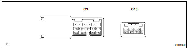
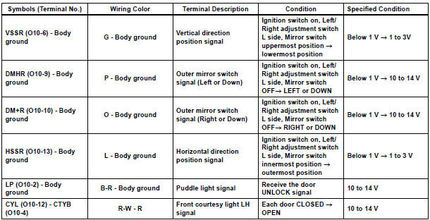
- Disconnect the O9 and O10 connectors.
- Measure the voltage and resistance according to the value(s) in the table below.
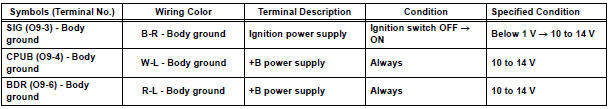
Voltage
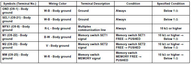
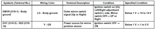
Resistance
If the result is not as specified, there may be a malfunction on the wire harness side.
- Reconnect the O9 and O10 connectors.
- Measure the voltage according to the value(s) in the table below
Voltage
If the result is not as specified, there may be a malfunction on the ECU side.
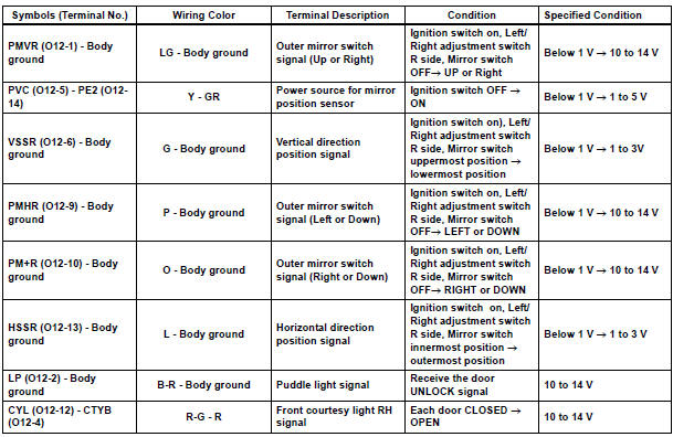
2. CHECK OUTER MIRROR CONTROL ECU RH
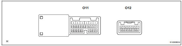
- Disconnect the O11 and O12 connectors.
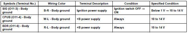
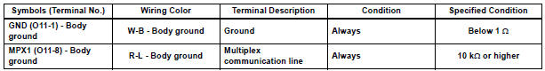
- Measure the voltage and resistance according to the value(s) in the table below.
Voltage
Resistance
If the result is not as specified, there may be a malfunction on the wire harness side.
- Reconnect the O11 and O12 connectors.
- Measure the voltage according to the value(s) in the table below.
Voltage
If the result is not as specified, there may be a malfunction on the ECU side.
 Problem symptoms table
HINT:
Use the table below to help determine the cause of the
problem symptoms. The potential causes of the symptoms
are listed in order of probability in the ''Suspected Area''
column ...
 Diagnosis system
1. DESCRIPTION
When troubleshooting a vehicle with the diagnosis
system, the only difference from the usual
troubleshooting procedure is connecting the
intelligent tester to the vehicl ...
Other materials:
Transfer oil
ON-VEHICLE INSPECTION
1. INSPECT TRANSFER OIL
(a) Remove the No. 1 plug and gasket.
(b) Check the oil level is within 0 - 5 mm (0 - 0.20 in.)
below the lowest end of the hole for No. 1 plug.
NOTICE:
When changing oil, recheck the oil level after
driving.
Excessively large or small ...
System Too Lean/ System Too Rich
DTC P0171 System Too Lean (Bank 1)
DTC P0172 System Too Rich (Bank 1)
DTC P0174 System Too Lean (Bank 2)
DTC P0175 System Too Rich (Bank 2)
DESCRIPTION
The fuel trim is related to the feedback compensation value, not to the basic
injection time. The fuel trim
consists of both the short-term ...
Diagnostic trouble code chart
If a malfunction code is displayed during the DTC check,
check the circuit listed for that code in the table below.
(Proceed to the page given for that circuit.)
POWER SLIDE DOOR SYSTEM
DTC No.
DTC No. Detection Item
Trouble Area
B2223
Power Slide Door ...
