Toyota Sienna Service Manual: Diagnosis system
1. DESCRIPTION
- When troubleshooting a vehicle with the diagnosis
system, the only difference from the usual
troubleshooting procedure is connecting the
intelligent tester to the vehicle and reading various
data output from the vehicle's clearance warning
ECU.
The clearance warning ECU records DTCs when the computer detects a malfunction in the computer itself or in its circuits.
To check the DTCs, connect the intelligent tester to the DLC3 on the vehicle. The intelligent tester enables you to erase the DTCs, activate the various actuators, and check the freeze frame data and Data List.
2. CHECK DLC3
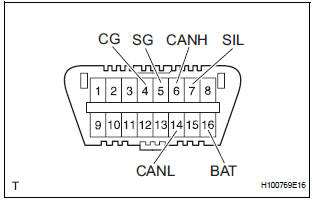
- The ECU uses ISO 15765-4 for communication.
The terminal arrangement of the DLC3 complies with SAE J1962 and matches the ISO 15765-4 format.
If the result is not as specified, the DLC3 may have a malfunction. Repair or replace the harness or connector.
Standard
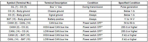
NOTICE: *: Before measuring the resistance, leave the vehicle as is for at least 1 minute and do not operate the ignition switch, any other switches or the doors.
HINT: Connect the cable of the intelligent tester to the DLC3, turn the power switch ON (IG) and attempt to use the tester. If the display indicates that a communication error has occurred, there is a problem either with the vehicle or with the tester.
- If communication is normal when the tester is connected to another vehicle, inspect the DLC3 of the original vehicle.
- If communication is still impossible when the tester is connected to another vehicle, the problem is probably in the tester itself, so consult the Service Department listed in the tester's instruction manual.
 Terminals of ECU
1. CHECK OUTER MIRROR CONTROL ECU LH
Disconnect the O9 and O10 connectors.
Measure the voltage and resistance according to
the value(s) in the table below.
Voltage
Resistance
If t ...
 Data list / active test
1. USING INTELLIGENT TESTER
Connect the intelligent tester to the DLC3.
Monitor the ECU data by following the prompts on
the tester screen.
HINT:
The intelligent tester has a & ...
Other materials:
Magnetic clutch relay
ON-VEHICLE INSPECTION
1. INSPECT MAGNETIC CLUTCH RELAY
(a) Remove the magnetic clutch relay.
(b) Measure the resistance according to the value(s) in
the table below.
Standard resistance
If the resistance is not as specified, replace the
magnetic clutch relay. ...
Short in Driver Side Squib 2nd Step Circuit
DTC B1180/17 Short in Driver Side Squib 2nd Step Circuit
DESCRIPTION
The driver side squib 2nd step circuit consists of the center airbag sensor
assembly, the spiral cable and
the steering pad.
The circuit instructs the SRS to deploy when deployment conditions are met.
DTC B1180/17 is rec ...
Master cylinder pressure sensor check (when using sst check wire)
(a) Leave the vehicle in a stationary condition and
release the brake pedal for 1 second or more, and
quickly depress the brake pedal with a force of 98 N
(10 kgf, 22 lbf) or more for 1 second or more.
(b) Check the ABS warning light stays on for 3
seconds.
HINT:
At this time, the ABS wa ...
