Toyota Sienna Service Manual: Removal
NOTICE: When installing, coat the parts indicated by the arrows with power steering fluid or molybdenum disulfide lithium base grease (See page PS-21).
1. INSPECT CENTER FRONT WHEEL
2. REMOVE FRONT WHEEL
3. SEPARATE TIE ROD ASSEMBLY LH SST 09628-62011
4. SEPARATE TIE ROD ASSEMBLY RH SST 09628-62011
HINT: Perform the same procedure on the other side.
5. SEPARATE STEERING INTERMEDIATE SHAFT ASSEMBLY
(a) Fix the steering wheel with the seat belt.
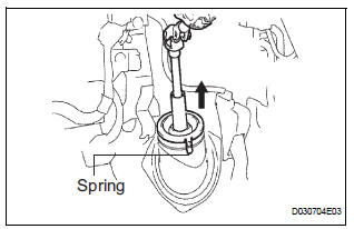
(b) Release the 3 springs and separate the dust cover.
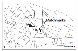
(c) Place matchmarks on the intermediate shaft assembly and power steering gear assembly.
(d) Remove the bolt and separate the intermediate shaft assembly.
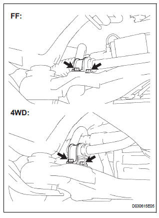
6. SEPARATE FRONT STABILIZER LINK ASSEMBLY LH
7. SEPARATE FRONT STABILIZER LINK ASSEMBLY RH
HINT: Perform the same procedure on the other side.
8. REMOVE FRONT STABILIZER BRACKET NO.1 LH
(a) Remove the 2 bolts and remove the stabilizer bracket No. 1.
9. REMOVE FRONT STABILIZER BRACKET NO.1 RH
HINT: Perform the same procedure on the other side.
10. DISCONNECT PRESSURE FEED TUBE ASSEMBLY
(a) Remove the clip and disconnect the return tube assembly from the power steering gear assembly.
(b) Using SST, disconnect the pressure feed tube assembly from the power steering gear assembly.
SST 09023-12701
(c) Remove the bolt and separate the tube clamp.
(d) Remove the nut and separate the tube clamp.
11. REMOVE RACK & PINION POWER STEERING GEAR ASSEMBLY
(a) Remove the 2 bolts, nuts and the power steering gear assembly.
NOTICE: Do not damage the 2 pressure tubes.
 Rack and pinion power steering gear
COMPONENTS
...
 Disassembly
1. REMOVE RETURN TUBE NO.2
(a) Using SST, remove the return tube No. 2.
SST 09023-12701
2. REMOVE STEERING LEFT TURN PRESSURE TUBE
(a) Using SST, remove the left turn pressure tube.
S ...
Other materials:
Random / Multiple Cylinder Misfire Detected
DESCRIPTION
When the engine misfires, high concentrations of hydrocarbons (HC) enter the
exhaust gas. High HC
concentration levels can cause increase in exhaust emission levels. Extremely
high concentrations of HC
can also cause increases in the Three-Way Catalytic Converter (TWC) tem ...
Steering wheel audio
switches
Some audio features can be controlled using the switches on
the steering wheel.
Operation may differ depending on the type of audio system or
navigation system. For details, refer to the manual provided with
the audio system or navigation system.
Operating the audio system using the steering ...
Repair
1. REPAIR REAR WINDOW DEFOGGER WIRE
Clean the broken wire tips with grease, wax and
silicone remover.
Place the masking tape along the both sides of the
wire.
Thoroughly mix the repair agent (Dupont paste No.
4817).
Using a fine tip brush, apply a smal ...
