Toyota Sienna 2010-2026 Owners Manual: The Blind Spot Monitor function detection areas
The areas that vehicles can be detected in are outlined below.
The range of the detection area extends to:
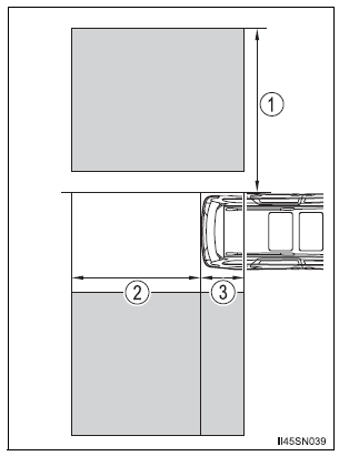
- Approximately 11.5 ft. (3.5 m) from the side of the vehicle The first 1.6 ft. (0.5 m) from the side of the vehicle is not in the detection area
- Approximately 9.8 ft. (3 m) from the rear bumper
- Approximately 3.3 ft. (1 m) forward of the rear bumper
| WARNING Cautions regarding the use of the system The driver is solely responsible for safe driving. Always drive safely, taking care to observe your surroundings. The Blind Spot Monitor function is a supplementary function which alerts the driver that a vehicle is present in the blind spot. Do not overly rely on the Blind Spot Monitor function. The function cannot judge if it is safe to change lanes, therefore over reliance could cause an accident resulting in death or serious injury. According to conditions, the system may not function correctly. Therefore the driver’s own visual confirmation of safety is necessary. |
The Blind Spot Monitor function is operational when
- The BSM main switch is set to on
- Vehicle speed is greater than approximately 10 mph (16 km/h).
The Blind Spot Monitor function will detect a vehicle when
- A vehicle in an adjacent lane overtakes your vehicle.
- Another vehicle enters the detection area when it changes lanes.
Conditions under which the Blind Spot Monitor function will not detect a vehicle
The Blind Spot Monitor function is not designed to detect the following types of vehicles and/or objects:
- Small motorcycles, bicycles, pedestrians etc.*
- Vehicles traveling in the opposite direction
- Guardrails, walls, signs, parked vehicles and similar stationary objects*
- Following vehicles that are in the same lane*
- Vehicles driving 2 lanes across from your vehicle*
*: Depending on conditions, detection of a vehicle and/or object may occur.
Conditions under which the Blind Spot Monitor function may not function correctly
- The Blind Spot Monitor function may not detect vehicles correctly in the following conditions:
- During bad weather such as heavy rain, fog, snow etc.
- When ice or mud etc. is attached to the rear bumper
- When driving on a road surface that is wet due to rain, standing water etc.
- When there is a significant difference in speed between your vehicle and the vehicle that enters the detection area
- When a vehicle is in the detection area from a stop and remains in the detection area as your vehicle accelerates
- When driving up or down consecutive steep inclines, such as hills, a dip in the road etc.
- When multiple vehicles approach with only a small gap between each vehicle
- When vehicle lanes are wide, and the vehicle in the next lane is too far away from your vehicle
- When the vehicle that enters the detection area is traveling at about the same speed as your vehicle
- When there is a significant difference in height between your vehicle and the vehicle that enters the detection area
- Directly after the BSM main switch is set to on
- When towing a trailer
- When items such as a bicycle carrier are installed on the rear of the vehicle
- Instances of the Blind Spot Monitor function unnecessarily detecting a vehicle and/or object may increase under the following conditions:
- When there is only a short distance between your vehicle and a guardrail, wall etc.
- When there is only a short distance between your vehicle and a following vehicle
- When vehicle lanes are narrow and a vehicle driving 2 lanes across from your vehicle enters the detection area
- When items such as a bicycle carrier are installed on the rear of the vehicle
 The Blind Spot Monitor function
The Blind Spot Monitor function uses radar sensors to detect vehicles
that are traveling in an adjacent lane in the area that is not reflected in
the outside rear view mirror (the blind spot), and a ...
 The Rear Cross Traffic Alert function
The Rear Cross Traffic Alert functions when your vehicle is in reverse.
It can detect other vehicles approaching from the right or left rear of
the vehicle. It uses radar sensors to alert the driv ...
Other materials:
Evaporative Emission System Reference Orifice
DTC SUMMARY
HINT:
The 0.02 inch orifice is located inside the pump module.
DESCRIPTION
The circuit description can be found in the EVAP (Evaporative Emission)
System (See page ES-409).
INSPECTION PROCEDURE
Refer to the EVAP System (See page ES-412).
MONITOR DESCRIPTION
5 hours*1 af ...
DTC check / clear
1. DTC CHECK
HINT:
When DTC B1150/23 is detected as a result of
troubleshooting for "Airbag System", perform
troubleshooting for the Occupant Classification System.
Check the DTCs.
Connect the intelligent tester to the DLC3
Turn the ignition switch to ...
Inspection
1. INSPECT SEAT HEATER SWITCH LH
Measure the resistance of the seat heater switch
when the switch is operated.
Resistance
If the result is not as specified, replace the switch.
HINT:
As the dial is being turned, the resistance changes
gradually.
Push the seat h ...
