Toyota Sienna Service Manual: Torque converter clutch and drive plate
Inspection
1. Inspect torque converter clutch assembly
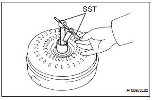
(a) Inspect the one-way clutch.
(1) Set SST into the inner race of the one-way clutch.
SST 09350-32014 (09351-32010) (2) Install SST so that it fits in the notch of the converter hub and outer race of the one-way clutch.
SST 09350-32014 (09351-32010, 09351- 32020) (3) Stand the torque converter up and turn the SST.
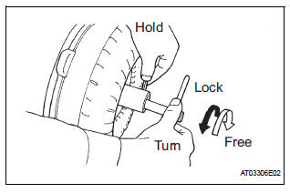
Standard: If the one-way clutch is turned clockwise, it rotates freely and if turned counterclockwise, it locks.
(b) Determine the condition of the torque converter clutch assembly.
(1) If the inspection result of the torque converter clutch assembly satisfies the following conditions, replace the torque converter clutch assembly.
Malfunction item: A metallic sound is emitted from the torque converter clutch assembly during the stall test or when the shift lever is moved to the N position.
The one-way clutch is free or locked in both directions.
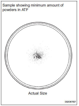
The amount of powder in the ATF is greater than the sample shown on the illustration (see the sample).
HINT: The sample shows the auto fluid of approximately 0.25 liters (0.26 US qts, 0.22 Imp. qts) that is taken out from the removed torque converter clutch.
(c) Exchange the ATF in the torque converter clutch.
(1) If the ATF is discolored and/or has a foul odor, completely stir the ATF in the torque converter clutch and drain it with the torque converter facing up.
(d) Clean and check the oil cooler and oil pipe line.
(1) If the torque converter clutch is inspected or the ATF is exchanged, clean the oil cooler and oil pipe line.
HINT:
- Spray compressed air of 196 kPa (2 kgf/cm 2, 28 psi) from the inlet hose.
- If plenty of fine powders are identified in the ATF, add new ATF using a bucket pump and clean it again.
(2) If the ATF is cloudy, inspect the oil cooler (radiator).
(e) Prevent deformation of the torque converter clutch and damage to the oil pump gear.
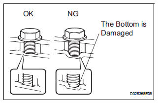
(1) When there is any damage on the end of the bolt for the torque converter clutch and on the bottom of the bolt hole, replace the bolt and the torque converter clutch.
(2) All of the bolts must be same length.
(3) Bolts with washers must be used.
2. INSPECT DRIVE PLATE & RING GEAR SUBASSEMBLY
(a) Set up a dial indicator with a roller instrument and measure the drive plate runout.
(b) Check for damage of the ring gear.
Maximum runout: 0.20 mm (0.0079 in.)
If runout is not within specification or ring gear is damaged, replace the drive plate.
 Installation
1. Install torque converter clutch assembly
(a) Install the torque converter clutch to the automatic
transaxle.
(b) Using vernier calipers and a straight edge, measure
the dimension "A& ...
 Automatic transaxle unit
COMPONENTS
...
Other materials:
Stop Light Switch Circuit Malfunction
DTC P0571 Stop Light Switch Circuit Malfunction
DESCRIPTION
The ECM receives the brake demand signal from the distance control ECU and
transmits it to the skid
control ECU (brake actuator assembly).
The skid control ECU (brake actuator assembly) receives a signal from the ECM
and operates ...
Door control transmitter
INSPECTION
1. INSPECT DOOR CONTROL TRANSMITTER
Inspect operation of the transmitter.
Remove the battery (lithium battery) from the transmitter.
Install a new or normal battery (lithium battery).
When a new or normal battery is not available,
connect 2 new ...
On-vehicle inspection
HINT:
The type of ignition switch on this model differs according to
the specifications of the vehicle. For the expressions used in
this section, refer to the "EXPRESSIONS OF IGNITION
SWITCH" precaution (See page ES-1).
1. CHECK AIR FUEL RATIO COMPENSATION SYSTEM
(a) Connect the inte ...
