Toyota Sienna Service Manual: Engine Coolant Temperature / Intake Air Temperature Correlation
DTC P011B Engine Coolant Temperature / Intake Air Temperature Correlation
DESCRIPTION
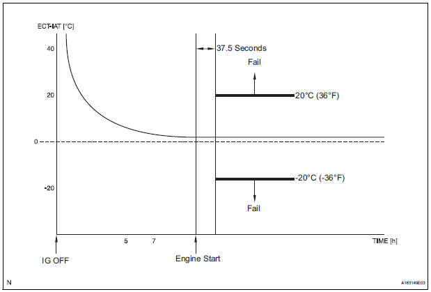
The ECM calculates the difference between the readings of the coolant temperature sensor and intake air temperature sensor. If the difference is greater than 20C (68F), the ECM will judge this as a malfunction and will set this DTC
|
DTC No. |
DTC Detection Condition |
Trouble Area |
|
P011B |
When conditions (a), (b), (c), (d) and (e) are met (2 trip
detection)
|
|
HINT:
- Waiting is required to prevent the temperature of the engine from affecting the readings. If the engine has been operated recently, it will not be possible to accurately compare the readings.
- For diagnosis, in order to duplicate the detection conditions of the DTC, it is necessary to park the vehicle for 7 hours. Parking the vehicle for 7 hours ensures that the actual temperature of the ECT and IAT are very similar. When the vehicle has been parked for less than 7 hours, differences in the readings may exist, this does not necessarily indicate a fault.
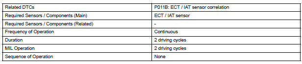
MONITOR STRATEGY
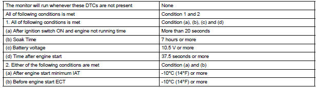
TYPICAL ENABLING CONDITIONS
TYPICAL MALFUNCTION THRESHOLDS

INSPECTION PROCEDURE
1 CHECK ANY OTHER DTCS OUTPUT (IN ADDITION P011B)
- Connect the intelligent tester to the DLC3.
- Turn the ignition switch to the ON position.
- Turn the tester on.
- Enter the following menus: DIAGNOSIS / ENHANCED OBD ll / DTC INFO / CURRENT CODES.
- Read the DTCs.
Result

HINT: If any DTCs other than P011B are output, troubleshoot those DTCs first

2 READ VALUE OF INTELLIGENT TESTER (INTAKE AIR TEMPERATURE)
- Leave the vehicle for 7 hours or more.
HINT: It is necessary leave the vehicle for 7 hours or more to allow conditions similar to the DTC detection conditions.
- Connect the intelligent tester to the DLC3.
- Turn the ignition switch to the ON position.
- Turn the tester ON.
- Enter the following menus: DIAGNOSIS / ENHANCED OBD ll / DATA LIST / PRIMARY / INTAKE AIR.
- Read the value displayed on the tester.
OK: The intake air temperature and the outside air temperature are within 10C (50F) of each other.
HINT: Temperature readings on the vehicle's outside temperature gauge (if equipped) are not suitable for comparing to the IAT reading. The outside temperature gauge has a significant delay built in to prevent temperature swings from being displayed on its display.
Use an accurate thermometer to determine the outside air temperature.
3 READ VALUE OF INTELLIGENT TESTER (COOLANT TEMPERATURE)
- Connect the intelligent tester to the DLC3.
- Turn the ignition switch to the ON position.
- Turn the tester ON.
- Enter the following menus: DIAGNOSIS / ENHANCED OBD ll / DATA LIST / PRIMARY / COOLANT TEMP.
OK: The coolant temperature and the outside air temperature are within 10C (50F) of each other.
HINT: If the result is not as specified, check that there are heat sources such as a block heater in the engine compartment.
REPLACE ECM
 Engine Coolant Temperature Circuit Range /
Performance Problem
Engine Coolant Temperature Circuit Range /
Performance Problem
DTC P0116 Engine Coolant Temperature Circuit Range /
Performance Problem
DESCRIPTION
Refer to DTC P0115
DTC No.
DTC Detection Condition
Trouble Area
P0116
...
 Throttle / Pedal Position Sensor / Switch "A/B"
Circuit
Throttle / Pedal Position Sensor / Switch "A/B"
Circuit
DTC P0120 Throttle / Pedal Position Sensor / Switch "A"
Circuit
DTC P0122 Throttle / Pedal Position Sensor / Switch "A"
Circuit Low Input
DTC P0123 Throttle / Pedal Position Se ...
Other materials:
Installation
1. Connect inlet sub-assembly
(a) Connect the inlet hose to the radiator.
(b) Install the inlet sub-assembly to the radiator with the
bolt.
Torque: 7.1 N*m (72 kgf*cm, 63 in.*lbf)V
2. Install no. 2 Radiator support
(A) install the no. 2 Radiator support to the radiator with
the 2 ...
Driving tips
Winter driving tips
Carry out the necessary preparations and inspections before
driving the vehicle in winter. Always drive the vehicle in a manner
appropriate to the prevailing weather conditions.
Preparation for winter
Use fluids that are appropriate to the prevailing outside temperatures. ...
Short to B+ in Front Passenger Side Squib 2nd
Step Circuit
DTC B1188/56 Short to B+ in Front Passenger Side Squib 2nd
Step Circuit
DESCRIPTION
The front passenger side squib 2nd step circuit consists of the center airbag
sensor assembly and the
front passenger airbag assembly.
The circuit instructs the SRS to deploy when deployment conditions are m ...
