Toyota Sienna Service Manual: Installation
1. Install torque converter clutch assembly
(a) Install the torque converter clutch to the automatic transaxle.
(b) Using vernier calipers and a straight edge, measure the dimension "A" between the transaxle fitting part of the engine and the converter fitting part of the drive plate (*1).
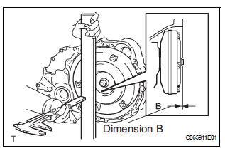
(c) Using vernier calipers and a straight edge, measure the dimension "B" shown in the illustration and check that "B" is greater than "A" (measured in step (*1)).
Standard: A + 1 mm (0.03937 in.) or more
| NOTICE: Remember to minus the thickness of the straight edge. |
2. INSTALL AUTOMATIC TRANSAXLE ASSEMBLY
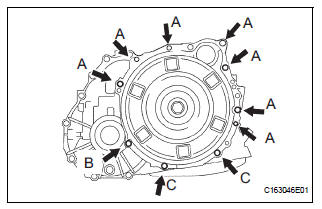
(a) Install the automatic transaxle to the engine with the 10 bolts
Torque: Bolt A 64 N*m (650 kgf*cm, 47 ft.*lbf) Bolt B 46 N*m (470 kgf*cm, 34 ft.*lbf) Bolt C 43 N*m (439 kgf*cm, 32 ft.*lbf)
(b) Apply a few drops of adhesive to each of 2 threads on the tip of the 6 torque converter clutch mounting bolts.
Adhesive: Part No. 08833-00070, THREE BOND 1324 or equivalent
(c) Install the 6 torque converter clutch mounting bolts.
Torque: 41 N*m (413 kgf*cm, 30 ft.*lbf)
| NOTICE: First install the black colored bolt, and then the remaining 5 bolts. |
(d) Install the flywheel housing under cover to the automatic transaxle with the 2 bolt.
Torque: 7.8 N*m (80 kgf*cm, 69 in.*lbf)
3. INSTALL ENGINE MOUNTING BRACKET FRONT
(a) Install the engine mounting bracket front to the automatic transaxle with the 3 bolts.
Torque: 64 N*m (653 kgf*cm, 47 ft.*lbf)
4. INSTALL TRANSMISSION OIL FILLER TUBE SUBASSEMBLY
(a) Coat a new O-ring with ATF, and install it to the transmission oil filler tube sub-assembly.
(b) Install the transmission oil filler tube sub-assembly and bolt to the automatic transaxle.
Torque: 5.5 N*m (56 kgf*cm, 49 in.*lbf) (c) Connect the 2 clamps to the oil filler tube.
(d) Install the ATF level gauge.
5. INSTALL OIL COOLER INLET TUBE NO.1
(a) Temporarily install the oil cooler outlet tube No.1.
(b) Temporarily install the oil cooler inlet tube No.1.
(c) Install the oil cooler tube clamp and bolt.
Torque: 5.5 N*m (56 kgf*cm, 49 in.*lbf)
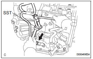
(d) Using SST and a wrench, tighten the oil cooler inlet tube No.1.
SST 09023-12701 Torque: 34 N*m (347 kgf*cm, 25 ft.*lbf)
6. INSTALL OIL COOLER OUTLET TUBE NO.1
(a) Using SST and a wrench, tighten the oil cooler outlet tube No.1.
SST 09023-12701 Torque: 34 N*m (347 kgf*cm, 25 ft.*lbf)
7. INSTALL TRANSMISSION CONTROL CABLE BRACKET NO.1
(a) Install the control cable bracket No.1 with the 2 bolts.
Torque: 12 N*m (122 kgf*cm, 9 ft.*lbf)
8. CONNECT CONNECTORS
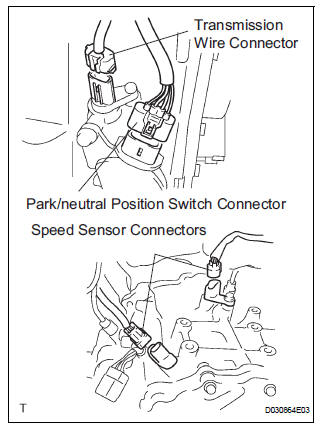
(a) Connect the transmission wire connector.
(b) Connect the park/neutral position switch connector.
(c) Connect the 2 speed sensor connectors.
9. INSTALL STARTER ASSEMBLY
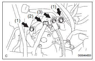
(a) Install the starter assembly with the 2 bolts (1).
Torque: 37 N*m (377 kgf*cm, 27 ft.*lbf) (b) Connect the connector (2).
(c) Connect the starter wire with the nut (3).
Torque: 9.8 N*m (100 kgf*cm, 87 in.*lbf)
10. CONNECT WIRE HARNESS
(a) Connect the wire harness with the bolt.
Torque: 13 N*m (133 kgf*cm, 10 ft.*lbf)
11. INSTALL WIRE HARNESS CLAMP
(a) Install the 2 clamps and 3 bolts.
Torque: 8.4 N*m (86 kgf*cm, 74 in.*lbf) (b) Connect the wire harnesses to the clamps.
12. INSTALL TRANSMISSION CONTROL CABLE CLAMP
(a) Install the transmission control cable clamp with the bolt.
Torque: 12 N*m (122 kgf*cm, 9 ft.*lbf)
13. INSTALL FRONT DRIVE SHAFT ASSEMBLY LH
HINT: (See page DS-17)
14. INSTALL FRONT DRIVE SHAFT ASSEMBLY RH
HINT: (See page DS-17)
15. INSTALL ENGINE ASSEMBLY WITH TRANSAXLE
HINT: (See page EM-44)
16. RESET MEMORY
HINT: (See page AX-16)
 Removal
1. REMOVE ENGINE ASSEMBLY WITH TRANSAXLE
HINT:
(See page EM-26)
2. REMOVE FRONT DRIVE SHAFT ASSEMBLY LH
HINT:
(See page DS-6)
3. REMOVE FRONT DRIVE SHAFT ASSEMBLY RH
HINT:
(See page DS-6)
4. ...
 Torque converter clutch and drive plate
Inspection
1. Inspect torque converter clutch assembly
(a) Inspect the one-way clutch.
(1) Set SST into the inner race of the one-way
clutch.
SST 09350-32014 (09351-32010)
(2) Install SS ...
Other materials:
Short to GND in Driver Side Squib Circuit
DTC B0102/11 Short to GND in Driver Side Squib Circuit
DESCRIPTION
The driver side squib circuit consists of the center airbag sensor assembly,
the spiral cable and the
steering pad.
The circuit instructs the SRS to deploy when deployment conditions are met.
DTC B0102/11 is recorded when ...
Short to B+ in Driver Side Squib Circuit
DTC B0103/12 Short to B+ in Driver Side Squib Circuit
DESCRIPTION
The driver side squib circuit consists of the center airbag sensor assembly,
the spiral cable and the
steering pad.
The circuit instructs the SRS to deploy when deployment conditions are met.
DTC B0103/12 is recorded when a ...
Removal
1. DISCONNECT CABLE FROM NEGATIVE BATTERY
TERMINAL
CAUTION:
Wait for 90 seconds after disconnecting the cable to prevent the airbag working
2. REMOVE FRONT SEAT ASSEMBLY
HINT:
Refer to the instructions for removal of the front seat assembly (for
flat type).
Refer to the ins ...
