Toyota Sienna Service Manual: Transmitter ID1 Operation Stop
DESCRIPTION
The tire pressure warning valve and transmitters that are installed in the tire and wheel assemblies measure the air pressures of the tires. The measured values are transmitted to the tire pressure warning antenna and receiver on the body as radio waves and then sent to the tire pressure warning ECU. The ECU compares the measured air pressure values with the air pressure threshold. When the measured air pressure value is less than this threshold, the warning light in the combination meter comes on. The tire pressure warning ECU stores a DTC when the tire pressure warning valve and transmitter stops transmitting signals. At this time, forcibly transmit the signals by releasing the tire pressure rapidly. The stored DTC is cleared when the signal transmission is resumed.
HINT: It is necessary to perform the procedure to identify the tire pressure warning valve and transmitter that is malfunctioning because it cannot be identified by the output DTC.
INSPECTION PROCEDURE
NOTICE: It is necessary to perform initialization (See page TW-23) after registration (See page TW-20) of the transmitter IDs into the tire pressure warning ECU after the ECU and/or valve and transmitter have been replaced.
1 PERFORM FORCED TRANSMISSION OF TRANSMITTER ID OF ALL WHEELS
(a) Set the tire pressure to the specified value.
Cold tire inflation pressure
(b) Make sure that the ignition switch is off.
(c) Connect the intelligent tester to the DLC3.
(d) Turn the ignition switch to the ON position and turn the tester on.
(e) Select "TIREPRESS" by following the prompts displayed on the intelligent tester.
TIRE PRESSURE: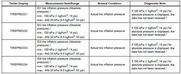
HINT: *: It may take about 5 to 6 minutes until the values are displayed. If the values are not displayed after about 5 to 6 minutes, perform troubleshooting according to the inspection procedure for DTCs C2121/21 to C2124/24 (See page TW-42).
(f) Rapidly release the pressures from each wheel by approximately 40 kPa (0.4 kgf/cm2, 5.8 psi) within 30 seconds.
(1) Check that each tire pressure data displayed on the intelligent tester screen has changed.
OK: Each tire pressure data displayed on the intelligent tester screen will change to the value of the tire pressure.
NOTICE:
- It takes about 5 to 6 minutes to display the updated tire pressure data.
- When the "TIREPRESS" data has not
changed, reset the tire pressure to the
appropriate specified value and rotate the tire
90 to 270 degrees (including the spare tire).
Then rapidly release the tire pressure and recheck it.
(2) After confirming that all of the tire pressure data displayed on the intelligent tester screen have changed, set the tire pressure to the appropriate specified values.
HINT: If the tire pressure data displayed on the intelligent tester screen has not changed after rechecking, go to other problem procedure (for malfunction in transmission or reception function (See page TW- 42)).

END
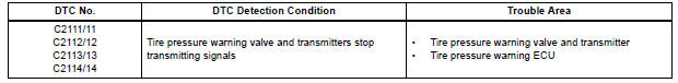
 Diagnostic trouble code chart
HINT:
If a trouble code is displayed during the DTC check, inspect
the circuit listed for that code. For details of each code, refer
to the relevant page listed under respective "DTC No." ...
 No Signal from Transmitter ID1
DESCRIPTION
The tire pressure warning valve and transmitters that are installed in the
tire and wheel assemblies
measure the air pressure of the tires. The measured values are transmitted to
...
Other materials:
Fail-safe chart
1. AUTO CANCEL FUNCTION (FAIL-SAFE FUNCTION):
HINT:
If a system malfunction occurs, the applicable DTCs will
appear on the multi-information display. In some cases,
a DTC will be set due to weather or vehicle operating
conditions, this does not indicate a system malfunction.
E3 (i ...
Disassembly
1. REMOVE FRONT DIFFERENTIAL RING GEAR
(a) Place matchmarks on the front differential ring gear
and differential case.
(b) Remove the 14 bolts.
(c) Using a plastic hammer, tap on the front differential
ring gear to remove it from the case.
2. REMOVE FRONT DIFFERENTIAL CASE FRONT TA ...
Front passenger occupant
classification system
Your vehicle is equipped with a front passenger occupant classification
system. This system detects the conditions of the front
passenger seat and activates or deactivates the devices for the
front passenger.
SRS warning light
Seat belt reminder light
“AIR BAG OFF” indicator light ...
