Toyota Sienna Service Manual: Disassembly
1. INSPECT UNDERDRIVE PACK CLEARANCE
HINT: (See page AX-262)
2. REMOVE UNDERDRIVE CLUTCH FLANGE NO.2 HOLE SNAP RING
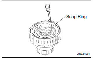
a) Using a screwdriver, remove the underdrive clutch flange No.2 snap ring.
3. REMOVE UNDERDRIVE CLUTCH DISC NO.1
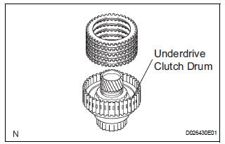
(a) Remove the flange, 4 discs and 4 plates from the underdrive clutch drum.
4. REMOVE UNDERDRIVE CLUTCH RETURN SPRING SUB-ASSEMBLY
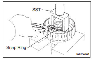
(a) Place SST on the clutch balancer and compress the spring with a press.
SST 09350-32014
(b) Using a snap ring expander, remove the snap ring.
NOTICE:
- Stop the press when the spring seat is lowered to the place 1 to 2 mm (0.039 to 0.078 in.) from the snap ring groove.
- This prevents the spring seat from being deformed.
- Do not expand the snap ring excessively.
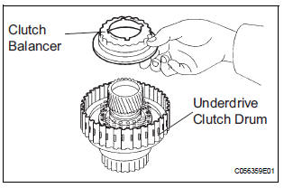
(c) Remove the clutch balancer from the underdrive clutch drum.
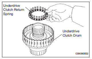
(d) Remove the return spring from the underdrive clutch drum.
5. REMOVE UNDERDRIVE CLUTCH PISTON SET
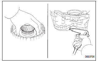
(a) Install the underdrive clutch to the transaxle case.
NOTICE: Be careful not to damage the oil seal ring.
(b) Holding the underdrive clutch piston by hand, apply compressed air (392 kPa, 4.0 kgf/cm2, 57 psi) to the transaxle case to remove the underdrive clutch piston.
6. REMOVE UNDERDRIVE CLUTCH DRUM O-RING
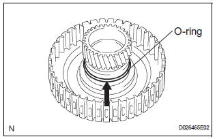
(a) Using a screwdriver, remove the O-ring from the underdrive clutch drum.
 Underdrive clutch
COMPONENTS
...
 Inspection
1. INSPECT UNDERDRIVE PACK CLEARANCE
(a) Install the underdrive clutch to the transaxle case.
NOTICE:
Be careful not to damage the oil seal rings.
(b) Install a dial indicator as shown in the ...
Other materials:
Removal
1. REMOVE ENGINE ASSEMBLY WITH TRANSAXLE
HINT:
(See page EM-34)
2. REMOVE TRANSVERSE ENGINE ENGINE MOUNTING INSULATOR
(a) Remove the 3 nuts and transverse engine engine
mounting insulator.
3. REMOVE FRONT SUSPENSION ARM SUBASSEMBLY LOWER NO.1 LH
(a) Remove the 2 bolts on the front sid ...
Noise Occurs from Generator while Engine is Running
INSPECTION PROCEDURE
1 CHECK LOOSENESS OF V-RIBBED BELT
(a) Check the tension of the belt by pushing it down with a
finger.
OK:
The tension of the belt is enough.
2 CHECK V-RIBBED BELT FOR WEAR
(a) Check the V-ribbed belt for wear.
OK:
The V-ribbed belt is not worn.
3 CHECK CLUTC ...
Installation
1. INSTALL REAR AXLE HUB & BEARING ASSEMBLY LH
(a) Install the hub & Bearing assembly LH with the 4
bolts.
Torque: 56 N*m (571 kgf*cm, 41 ft.*lbf)
2. INSPECT BEARING BACKLASH (See page AH-16)
3. INSPECT AXLE HUB DEVIATION (See page AH-16)
4. CONNECT SKID CONTROL SENSOR WIRE
(a) Co ...
