Toyota Sienna Service Manual: Unlock Warning Switch Circuit
DESCRIPTION
The unlock warning switch detects if the key is in the ignition key cylinder.
The unlock warning switch turns on when the key is inserted into the ignition key cylinder and turns off when the key is removed from the cylinder.
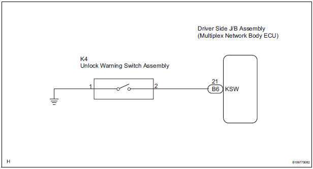
The body ECU is connected to the unlock warning switch via terminal KSW and key detection status signals are input to the ECU.
The body ECU applies voltage to the unlock warning switch via terminal KSW. When the unlock warning switch is on (there is continuity between the switch terminals), a signal indicating that the key is in the ignition key cylinder is input to the body ECU. When the switch is off (there is no continuity between the switch terminals), a signal indicating that the key is not in the cylinder is input.
WIRING DIAGRAM
INSPECTION PROCEDURE
1 READ VALUE OF DATA LIST (UNLOCK WARNING SWITCH)
- Check the DATA LIST to ensure proper function of the door unlock detection switch.
BODY:
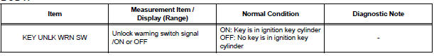
OK: The display is as specified in the normal condition.
PROCEED TO NEXT CIRCUIT INSPECTION SHOWN IN PROBLEM SYMPTOMS TABLE
2 INSPECT UNLOCK WARNING SWITCH ASSEMBLY
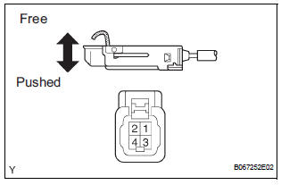
- Remove the unlock warning switch assembly.
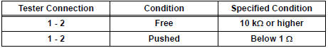
- Measure the resistance according to the value(s) in the table below.
Standard resistance
3 CHECK WIRE HARNESS (UNLOCK WARNING SWITCH - DRIVER SIDE J/B)
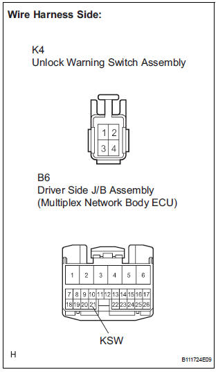
- Disconnect the K4 unlock warning switch assembly connector.
- Disconnect the B6 driver side J/B connector.
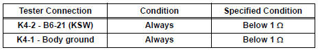
- Measure the resistance according to the value(s) in the table below.
Standard resistance
PROCEED TO NEXT CIRCUIT INSPECTION SHOWN IN PROBLEM SYMPTOMS TABLE
 Data list / active test
1. READ DATA LIST
HINT:
Using the intelligent tester's DATA LIST allows switch,
actuator and other item values to be read without
removing any parts. Reading the DATA LIST early in
troubleshootin ...
 Transmitter battery
REPLACEMENT
1. REMOVE TRANSMITTER BATTERY
NOTICE:
Special caution should be taken for handling each
component as they are precision electronic
components.
Using a coin or the equiva ...
Other materials:
Sliding doors
Vehicles without power sliding doors
The sliding doors can be opened and closed using the sliding
door handle. The sliding door can be locked and unlocked using
the wireless remote control, door lock switch or inside lock
knob.
Vehicles with power sliding doors
...
Installation
HINT:
Use the same procedures for the RH side and LH side.
The procedures listed below are for the LH side.
1. INSTALL CURTAIN SHIELD AIRBAG ASSEMBLY LH
Install the curtain shield airbag assembly LH with
the 13 bolts in the order shown in the illustration.
Torque: 14 N*m ...
Handling of hose clamps
HANDLING OF HOSE CLAMPS
(a) Before removing the hose, check the clamp position
so that it can be reinstalled in the same position.
(b) Replace any deformed or dented clamps with new
ones.
(c) When reusing a hose, attach the clamp on the
clamp track portion of the hose.
(d) For a s ...
