Toyota Sienna Service Manual: Panel Switch Error/ Touch Switch Error
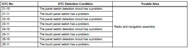
DTC 21-10 Panel Switch Error
DTC 21-11 Touch Switch Error
DTC 23-10 Panel Switch Error
DTC 23-11 Touch Switch Error
DTC 24-10 Panel Switch Error
DTC 24-11 Touch Switch Error
DTC 25-10 Panel Switch Error
DTC 25-11 Touch Switch Error
DESCRIPTION
INSPECTION PROCEDURE
HINT: After the inspection is completed, clear the DTCs.
1 REPLACE RADIO AND NAVIGATION ASSEMBLY
END
 ON / OFF Indication Parameter Error
DTC 01-E2 ON / OFF Indication Parameter Error
DESCRIPTION
DTC No.
DTC Detection Condition
Trouble Area
01-E2
The signal for ON/OFF control from the master device ...
 Error in Picture Circuit/ No Current in Back-light/ Excess Current in
Back-light
Error in Picture Circuit/ No Current in Back-light/ Excess Current in
Back-light
DTC 34-10 Error in Picture Circuit
DTC 34-11 No Current in Back-light
DTC 34-12 Excess Current in Back-light
DESCRIPTION
DTC No.
DTC Detection Condition
Trouble Area
...
Other materials:
Cruise Main Indicator Light Circuit
DESCRIPTION
When the cruise control main switch is on, the CRUISE main indicator light
and READY indicator light
come on. This indicates the control condition (presence or absence of a vehicle
in front, vehicle-to-vehicle
distance, and set vehicle speed) and fail-safe state through the multip ...
Mute Signal Circuit between Radio Receiver and Stereo Component
Amplifier
DESCRIPTION
This circuit sends a signal to the stereo component amplifier to mute noise.
Because of that, the noise
produced by changing the sound source ceases.
If there is an open in the circuit, noise can be heard from the speakers when
changing the sound source.
If there is a short i ...
Installation
1. INSTALL RACK & PINION POWER STEERING GEAR ASSEMBLY
(a) Install the power steering gear assembly with the 2
bolts and nuts.
Torque: 70 N*m (714 kgf*cm, 52 ft.*lbf)
2. CONNECT PRESSURE FEED TUBE ASSEMBLY
(a) Connect the pressure feed tube assembly to the
power steering gear asse ...
