Toyota Sienna Service Manual: Removal
1. DRAIN ENGINE COOLANT
2. REMOVE V-BANK COVER SUB-ASSEMBLY
3. REMOVE NO. 2 AIR CLEANER INLET
4. REMOVE NO. 1 AIR CLEANER INLET
5. REMOVE AIR CLEANER CAP SUB-ASSEMBLY
6. REMOVE AIR CLEANER CASE SUB-ASSEMBLY
7. REMOVE ENGINE COOLANT TEMPERATURE SENSOR
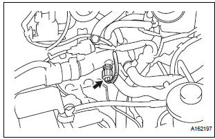
- Remove the engine coolant temperature sensor connector.
- Remove the engine coolant temperature sensor.
 Engine coolant temperature sensor
COMPONENTS
...
 Inspection
1. INSPECT ENGINE COOLANT TEMPERATURE SENSOR
Using an ohmmeter, measure the resistance
between the terminals.
Standard resistance
If the result is as specified, do not replace ...
Other materials:
Evaporator temperature sensor
ON-VEHICLE INSPECTION
1. INSPECT A/C EVAPORATOR TEMPERATURE SENSOR
(a) Remove the A/C evaporator temperature sensor (A/
C thermistor).
(b) Disconnect the connector from the A/C evaporator
temperature sensor (A/C thermistor).
(c) Measure the resistance according to the value(s) in
the ...
Short to B+ in Side Squib LH Circuit
DTC B0118/46 Short to B+ in Side Squib LH Circuit
DESCRIPTION
The side squib LH circuit consists of the center airbag sensor assembly and
the front seat side airbag
assembly LH (side squib LH).
This circuit instructs the SRS to deploy when deployment conditions are met.
DTC B0118/46 is re ...
Cooling fan relay
On-vehicle inspection
1. Cooling fan relay
(a) Remove the relay from engine room relay block No.
1.
(b) Measure the resistance of the relay.
Standard resistance
If the result is not as specified, replace the cooling
fan relay.
(c) Install the relay to engine room relay block No. ...
