Toyota Sienna Service Manual: Reassembly
1. INSTALL GENERATOR ROTOR ASSEMBLY
(a) Place the drive end frame on the clutch pulley.
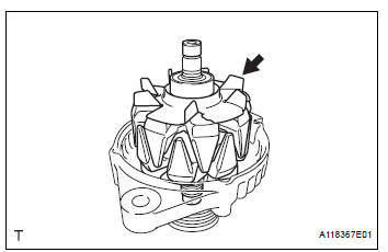
(b) Install the generator rotor assembly to the drive end frame.
(c) Place a new generator washer on the generator rotor.
2. INSTALL GENERATOR COIL ASSEMBLY
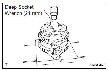
(a) Using a deep socket wrench (21 mm) and a press, slowly press in the generator coil assembly.
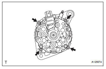
(b) Install the 4 bolts.
Torque: 5.8 N*m (59 kgf*cm, 51 in.*lbf)
3. INSTALL GENERATOR BRUSH HOLDER ASSEMBLY
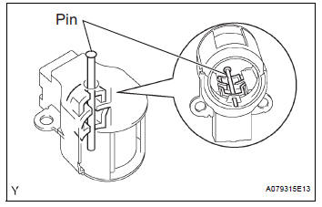
(a) While pushing the 2 brushes into the generator brush holder assembly, insert a φ1.0 mm (0.039 in.) pin into the brush holder hole.
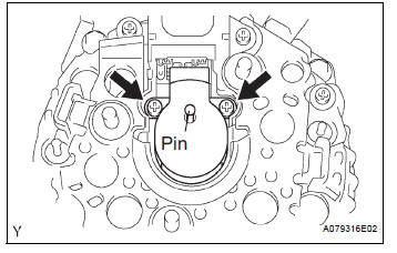
(b) Install the brush holder assembly to the generator coil with the 2 screws.
Torque: 1.8 N*m (18 kgf*cm, 16 in.*lbf) (c) Pull out the pin from the generator brush holder.
4. INSTALL GENERATOR TERMINAL INSULATOR
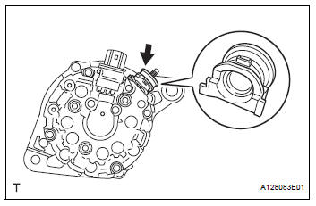
(a) Install the terminal insulator to the generator coil.
| NOTICE: Pay attention to installation direction of the terminal insulator. |
5. INSTALL GENERATOR REAR END COVER
(a) Install the generator rear end cover to the generator coil with the 3 nuts.
Torque: 4.6 N*m (47 kgf*cm, 41 in.*lbf)
6. INSTALL GENERATOR CLUTCH PULLEY
(a) Temporarily install the clutch pulley onto the rotor shaft.
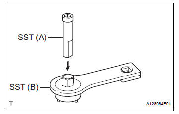
(b) Set SST (A) and (B).
SST 09820-63020
(c) Clamp SST (A) in a vise.
| NOTICE: Be sure to fix the flat surface of SST (A) in a vise. |
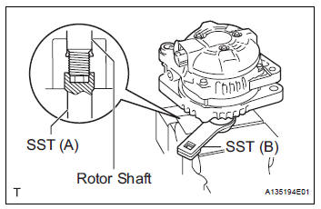
(d) Place the rotor shaft end into SST (A).
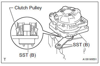
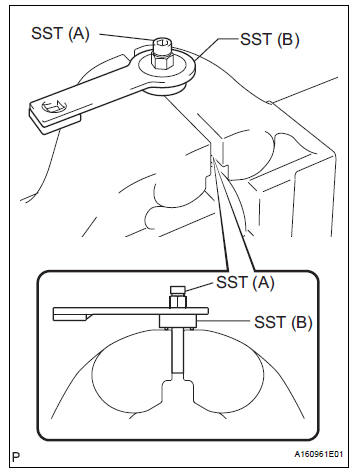
(e) Fit SST (B) to the clutch pulley.
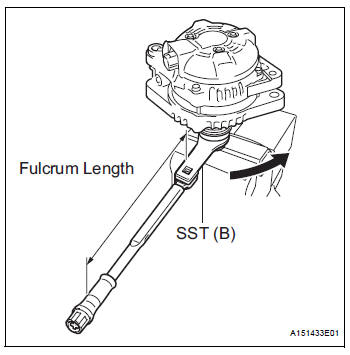
(f) Tighten the pulley by turning SST (B) in the direction shown in the illustration.
Torque: without SST 110 N*m (1125 kgf*cm, 81 ft.*lbf)
with SST 84 N*m (857 kgf*cm, 62 ft.*lbf)
NOTICE:
|
(g) Remove the generator assembly from SST.
(h) Check that the clutch pulley rotates smoothly.
(i) Install a new clutch pulley cap to the clutch pulley.
 Replacement
1. REPLACE GENERATOR DRIVE END FRAME BEARING
(a) Remove the 4 screws and retainer plate from the
drive end frame.
(b) Using SST and a hammer, tap out the drive end
frame bearing from the d ...
 Installation
1. Install generator assembly
(a) Install the bracket with the bolt.
Torque: 20 N*m (204 kgf*cm, 15 ft.*lbf)
(b) Install the wire harness clamp stay.
Torque: 8.4 N*m (86 kgf*cm, 74 in. ...
Other materials:
Open in Driver Side Squib Circuit
DTC B0101/14 Open in Driver Side Squib Circuit
DESCRIPTION
The driver side squib circuit consists of the center airbag sensor assembly,
the spiral cable and the
steering pad.
The circuit instructs the SRS to deploy when deployment conditions are met.
DTC B0101/14 is recorded when an open ...
Adjustment
1. VEHICLE PREPARATION FOR HEADLIGHT AIMING
ADJUSTMENT
Prepare the vehicle:
Ensure there is no damage or deformation to the
body around the headlights.
Fill the fuel tank.
Make sure that the oil is filled to the specified
level.
Make sure that the c ...
Absence of Registration Unit/ No Response for Connection Check/ Last Mode
Error/ No Response Against ON / OFF Command/ Mode Status Error/ Slave Reset
DESCRIPTION
HINT:
*1: Even if no fault is present, this trouble code may be stored
depending on the battery condition or
engine start voltage.
*2: If the power connector is disconnected after the engine
starts, this code is stored after 180 seconds.
*3: If the ...
