Toyota Sienna Service Manual: Vehicle Speed Signal Error (Test Mode DTC)
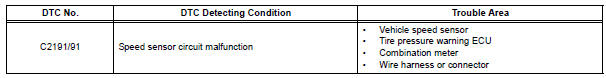
DTC C2191/91 Vehicle Speed Signal Error (Test Mode DTC)
DESCRIPTION
The tire pressure warning ECU receives a speed signal from the combination meter. This DTC is stored upon entering test mode, and cleared when a vehicle speed signal of 12 mph (20 km/h) is detected for 3 seconds or more. This DTC is output only in test mode.
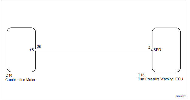
WIRING DIAGRAM
INSPECTION PROCEDURE
NOTICE:
- When replacing the tire pressure warning ECU, read the IDs stored in the ECU using the intelligent tester and write them down before removal.
- It is necessary to perform initialization (See page TW-23) after registration (See page TW-20) of the transmitter IDs into the tire pressure warning ECU after the ECU has been replaced.
1 READ VALUE ON INTELLIGENT TESTER
(a) Make sure that the ignition switch is off.
(b) Connect the intelligent tester to the DLC3.
(c) Turn the ignition switch to the ON position.
(d) Select the item below in the Data List, and read the value displayed on the intelligent tester.
HINT: Enter the following menus: DIAGNOSIS / OBD/MOBD / METER / DATA LIST.
METER:
(e) Check that the values indicated on the tester and on the combination meter are the same.
OK: Vehicle speed indicated on the intelligent tester indicates the actual speed.

2 CHECK HARNESS AND CONNECTOR (ECU - COMBINATION METER)
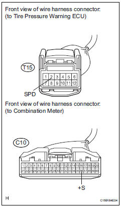
(a) Disconnect the T15 ECU connector.
(b) Disconnect the C10 meter connector.
(c) Measure the resistance according to the value(s) in the table below.
Standard resistance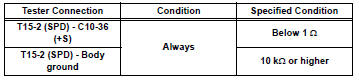

REPLACE TIRE PRESSURE WARNING ECU (See page TW-87)
 Initialization not Completed
DTC C2177/77 Initialization not Completed
DESCRIPTION
Initialization is necessary after replacing any of the ECUs, tires with
different tire pressure, or tire pressure
warning valve and transmitt ...
 Tire Pressure Warning Reset Switch Circuit
DESCRIPTION
The ECU enters the initialization mode and performs initialization
automatically, when the tire pressure
warning ECU receives the signal from the tire pressure warning reset switch. If ...
Other materials:
Disassembly
1. REMOVE FRONT DIFFERENTIAL RING GEAR
(a) Place matchmarks on the front differential ring gear
and differential case.
(b) Remove the 14 bolts.
(c) Using a plastic hammer, tap on the front differential
ring gear to remove it from the case.
2. REMOVE FRONT DIFFERENTIAL CASE FRONT TA ...
Disassembly
1. REMOVE INDICATOR LIGHT WIRE SUB-ASSEMBLY
(a) Remove the indicator light wire sub assembly from
the position indicator light guide.
2. REMOVE POSITION INDICATOR LIGHT BULB
(a) Remove the shift position indicator light bulb from
the indicator light wire sub-assembly
3. REMOVE POSITION IND ...
Display Signal Circuit between Television Display Assembly and Radio
and Navigation Assembly
DESCRIPTION
This circuit sends a DVD image signal from the television display assembly to
the radio and navigation
assembly.
WIRING DIAGRAM
INSPECTION PROCEDURE
1 CHECK HARNESS AND CONNECTOR (RADIO AND NAVIGATION ASSEMBLY - TELEVISION
DISPLAY ASSEMBLY)
Disconnect the radio and n ...
