Toyota Sienna Service Manual: When servicing full-time 4wd vehicles
The full-time 4WD SIENNA is equipped with the open center differential system.
If incorrect preparations or test procedures are used, the test will not only be unsuccessful, but may be dangerous as well.
Therefore, before beginning any such servicing or test, be sure to check the following items:
- Whether wheels should be touching ground or jacked up
- Transaxle gear position
- Maximum testing vehicle speed
- Maximum testing time
(a) Before Beginning Test
This vehicle does not have a center diff. lock mode or 4WD (Normal) Mode to allow only the front or rear wheel to be rotated.
The test method for this vehicle is different from that for vehicles equipped with the center diff. lock mode or 4WD (Normal) Mode, so make sure to use the correct test method.
 Braking Force Test
(Vehicle Speed: Below 0.5 km/h or 0.3 mph) When performing low-speed type brake tester measurements, observe the following instructions.
(1) Position the wheels to be tested (front or rear) on the tester.
(2) Shift the transaxle shift lever to "N" position.
(3) Idle the engine, operate the brake booster and perform the test.
(c) Speedometer Test or Other Tests
(Using Speedometer Tester or Chassis Dynamometer)
When performing test at high speed or high load, use the methods shown below.
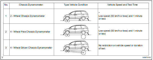
*: This is to avoid damaging the center differential.
(d) On-Vehicle Wheel Balancing
On-Vehicle Wheel Balancing
When doing on-vehicle wheel balancing on a fulltime 4WD vehicle, to prevent the wheels from rotating at different speeds in different directions from each other (which could damage the center differential), always be sure to observe the following precautions:
(1) All 4 wheels should be jacked up, clearing the ground completely.
(2) The parking brake lever should be fully released.
(3) None of the brakes should be allowed to drag.
(4) The wheels should be driven on the wheel balancer with the engine running.
HINT:
When doing this, be careful of the other wheels, which will rotate at the same time.
(5) Avoid sudden acceleration, deceleration and braking.
(6) Carry out wheel balancing with the transaxle in D position.
 For vehicles equipped with mobile communication systems
FOR VEHICLES EQUIPPED WITH MOBILE COMMUNICATION SYSTEMS
(a) Install the antenna far away from the ECU and
sensors of the vehicle electronic systems as
possible.
(b) Install an antenna feeder ...
 For vehicles equipped with traction control (trac) system
When using a 2-wheel drum tester such as a
speedometer tester or chassis dynamometer, etc., or
jacking up the front wheels and driving the wheels,
always push in the TRAC cut ("TRAC OFF") ...
Other materials:
Removal
1. DRAIN BRAKE FLUID
NOTICE:
Wash brake fluid off immediately if it adheres to any
painted surface.
2. DISCONNECT BATTERY NEGATIVE TERMINAL
3. REMOVE AIR CLEANER ASSEMBLY WITH HOSE
4. REMOVE BRAKE ACTUATOR WITH BRACKET
(a) Release the latch of the brake actuator connector to
disconnect the c ...
Installation
1. INSTALL WINDSHIELD WIPER MOTOR ASSEMBLY
Apply MP grease to the crank arm pivot of the
windshield wiper motor assembly.
Install the windshield wiper motor assembly with the
3 bolts to the windshield wiper link assembly.
Torque: 7.5 N*m (76 kgf*cm, 66 in.*lbf)
2. INST ...
DTC check / clear
HINT:
Illustrations may differ from the actual vehicle depending
on the device settings and options. Therefore, some
detailed areas may not be shown exactly the same as on
the actual vehicle.
If the system cannot enter the diagnostic mode, inspect all AVC-LAN
communication ...
