Toyota Sienna Service Manual: Adjustment
1. VEHICLE PREPARATION FOR FOG LIGHT AIMING
- Prepare the vehicle:
- Ensure there is no damage or deformation to the body around the fog lights.
- Fill the fuel tank.
- Make sure that the oil is filled to the specified level.
- Make sure that the coolant is filled to the specified level.
- Inflate the tires to the appropriate pressure.
- Place the spare tire, tools, and jack in their original positions.
- Unload the trunk.
- Sit a person of average weight (68 kg, 150 lb) in the driver's seat.
2. PREPARATION FOR FOG LIGHT AIMING
- Prepare the vehicle according to the following conditions:
- Place the vehicle in a location that is dark enough to clearly observe the cutoff line. The cutoff line is a distinct line, below which light from the fog lights can be observed and above which it cannot.
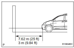
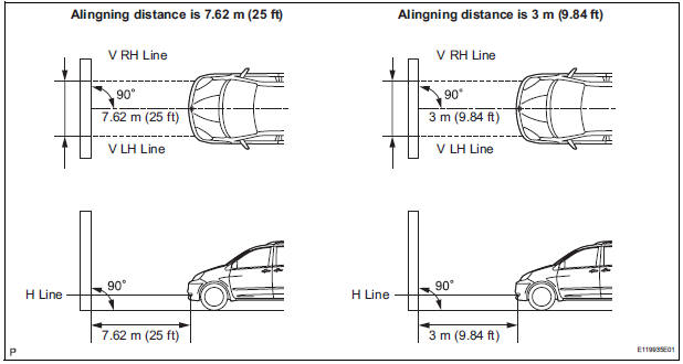
- Place the vehicle at a 90 angle to the wall.
- Create a 7.62 m (25 ft) distance between the vehicle (fog light bulb center) and the wall.
- Place the vehicle on a level surface.
- Bounce the vehicle up and down to settle the suspension.
NOTICE: A distance of 7.62 m (25 ft) between the vehicle (fog light bulb center) and the wall is necessary for proper aim adjustment. If unavailable, secure a distance of exactly 3 m (9.84 ft) for check and adjustment. (The target zone will change with the distance, so follow the instructions in the illustration.)
- Prepare a piece of thick white paper (approximately 2 m (6.6 ft) (height) x 4 m (13.1 ft) (width)) to use as a screen.
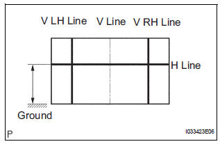
- Draw a vertical line down the center of screen (V line).
- Set the screen as shown in the illustration.
HINT:
- Stand the screen perpendicular to the ground.
- Align the V line on the screen with the center of the vehicle.
- Draw base lines (H line, V LH, V RH lines) on the screen as shown in the illustration.
HINT: Mark the fog light bulb center marks on the screen.
If the center mark cannot be observed on the fog light, use the center of the fog light bulb or the manufacturer's name marked on the fog light as the center mark.
- H Line (Fog light height): Draw a horizontal line across the screen so that it passes through the center marks. The H line should be at the same height as the fog light bulb center marks of the low-beam fog lights.
- V LH Line, V RH Line (Center mark position of left-hand (LH) and right-hand (RH) fog lights): Draw two vertical lines so that they intersect the H line at each center mark.
3. FOG LIGHT AIMING INSPECTION
- Cover or disconnect the connector of the fog light on the opposite side to prevent light from the fog light not being inspected from affecting fog light aiming inspection.
- Start the engine.
NOTICE: Engine rpm must be 1,500 or more.
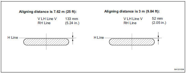
- Turn on the fog light and make sure that the cutoff line falls within the specified area, as shown in the illustration.
4. FOG LIGHT AIMING ADJUSTMENT
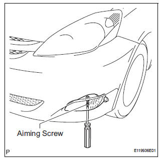
- Adjust the fog light aim into the specified range by turning aiming screw with a screwdriver.
NOTICE: The final turn of the aiming screw should be made in the clockwise direction. If the screw is tightened excessively, loosen it and then retighten it, so that the final turn of the screw is in the clockwise direction.
 Components
REMOVAL
1. DISCONNECT CABLE FROM NEGATIVE BATTERY
TERMINAL
2. REMOVE FRONT BUMPER ASSEMBLY
3. REMOVE FOG LIGHT ASSEMBLY
Disengage the 2 claws
Disengage the 2 pins and rem ...
 Reassembly
1. INSTALL FOG LIGHT BULB
Turn in the direction indicated by the arrow and
install the fog light bulb.
...
Other materials:
Removal
1. DRAIN POWER STEERING FLUID
2. REMOVE FRONT WHEEL RH
3. REMOVE FRONT FENDER APRON SEAL RH (See
page EM-26)
4. REMOVE FAN AND GENERATOR V BELT (See page
EM-6)
5. DISCONNECT NO. 1 FLUID RESERVOIR TO PUMP HOSE
(a) Slide the clip and disconnect the No. 1 fluid
reservoir to pump hose from t ...
Light Control Switch Circuit
DESCRIPTION
This circuit detects the state of the headlight dimmer switch.
WIRING DIAGRAM
INSPECTION PROCEDURE
1 READ VALUE OF INTELLIGENT TESTER
Connect the intelligent tester to DLC3.
Turn the ignition switch ON and push the intelligent
tester main switch ON.
Select t ...
Removal
1. DISCONNECT CABLE FROM NEGATIVE BATTERY
TERMINAL
CAUTION:
Wait for 90 seconds after disconnecting the cable to
prevent the airbag working.
2. REMOVE FRONT SEAT ASSEMBLY
HINT:
Refer to the instructions for removal of the front seat
assembly (for flat type).
Refer to the in ...
