Toyota Sienna Service Manual: Components
REMOVAL
1. DISCONNECT CABLE FROM NEGATIVE BATTERY TERMINAL
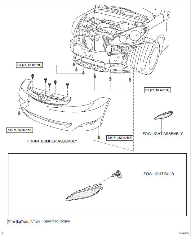
2. REMOVE FRONT BUMPER ASSEMBLY
3. REMOVE FOG LIGHT ASSEMBLY
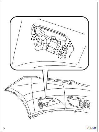
- Disengage the 2 claws
- Disengage the 2 pins and remove the fog light assembly.
DISASSEMBLY
1. REMOVE FOG LIGHT BULB
- Turn in the direction indicated by the arrow and remove the fog light bulb.

 Adjustment
1. VEHICLE PREPARATION FOR FOG LIGHT AIMING
Prepare the vehicle:
Ensure there is no damage or deformation to the
body around the fog lights.
Fill the fuel tank.
...
Other materials:
Inspection
1. INSPECT OUTER REAR VIEW MIRROR ASSEMBLY LH (w/o Memory)
Disconnect the mirror connector.
Check operation of the outer mirror.
Apply battery voltage and inspect operation of
the mirror face, as shown in the table and
illustration.
Standard (LH)
If the result i ...
Trailer Tongue Weight
A recommended tongue weight varies in accordance with the types
of trailers or towing as described below.
To ensure the recommended values shown below, the trailer must
be loaded by referring to the following instructions.
Tongue Weight
The gross trailer weight should be distribute ...
TC and CG Terminal Circuit
DESCRIPTION
Connecting terminals TC and CG of the DLC3 causes the ECU to display the DTC
by blinking the ABS
warning light and/or VSC warning light.
WIRING DIAGRAM
INSPECTION PROCEDURE
NOTICE:
When replacing the brake actuator assembly, perform zero point calibration
(See page BC-70).
...
