Toyota Sienna Service Manual: Disassembly
HINT: On the RH side, use the same procedures as on the LH side.
1. REMOVE FRONT DOOR LOWER FRAME BRACKET GARNISH LH
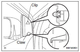
- Using a screwdriver, disengage the clip and claw, and remove the garnish.
HINT: Tape the screwdriver tip before use.
2. REMOVE FRONT DOOR INSIDE HANDLE BEZEL PLUG LH
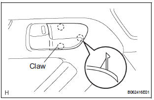
- Using a screwdriver, disengage the 3 claws and remove the bezel.
HINT: Tape the screwdriver tip before use
3. REMOVE POWER WINDOW REGULATOR MASTER SWITCH ASSEMBLY
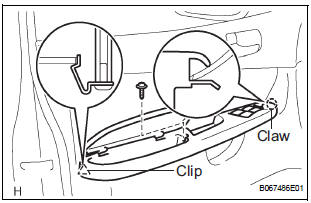
- Remove the screw.
- Using a screwdriver, disengage the clip and claw,
and remove the armrest base panel upper together
with the switch.
HINT: Tape the screwdriver tip before use.
- Disconnect the connector.
- Remove the 3 screws and switch from the armrest base panel upper.
- Using pliers, remove the 2 pins and armrest.
4. REMOVE FRONT DOOR TRIM BOARD SUBASSEMBLY LH
- Remove the 3 screws and back frame plate.
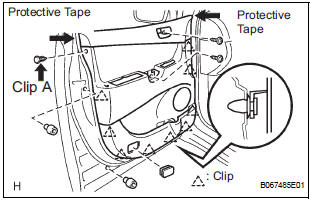
- Remove the 2 cushion rubbers.
- Remove the 2 screws and the clip A.
- Using a screwdriver, disengage the other 9 clips.
HINT: Tape the screwdriver tip before use.
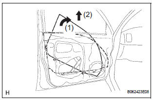
- Remove the trim board upward.
HINT: In order to prevent the door panel from being damaged, cover the areas indicated by arrow marks in the illustration with protective tape.
- Disconnect the 2 cables from the inside handle, as shown in the illustration.
- Using a screwdriver, disengage the 10 hooks and
remove the weatherstrip inner.
HINT: Tape the screwdriver tip before use.
- Remove the 2 screws and inside handle.
5. REMOVE FRONT DOOR SERVICE HOLE COVER LH
- Remove the screw and reinforcement No. 1.
- Remove the service hole cover.
NOTICE: Remove the tape remaining on the door side.
6. REMOVE OUTER REAR VIEW MIRROR ASSEMBLY LH
- Disconnect the connector.
- Remove the 3 nuts and mirror.
NOTICE: When the nuts are removed, the mirror assembly may fall and become deformed.
7. REMOVE FRONT NO.1 SPEAKER ASSEMBLY (See page AV-206)
8. REMOVE FRONT DOOR WINDOW FRAME MOULDING REAR LH (See page ET-30)
9. REMOVE FRONT DOOR GLASS WEATHERSTRIP ASSEMBLY OUTER LH (See page ET-21)
10. REMOVE FRONT DOOR GLASS SUB-ASSEMBLY LH
HINT: Insert a shop rag inside the door panel to prevent the door glass from being scratched.
- Open the door glass until the bolts appear in the service holes.
- Remove the 2 bolts holding the door glass to the window regulator.
- Remove the door glass in the direction indicated by the arrow mark in the illustration.
NOTICE:
- Do not damage the door glass.
- When the bolts are removed, the door glass may fall and become deformed.
- Remove the glass run.
11. REMOVE FRONT DOOR WINDOW REGULATOR SUB-ASSEMBLY LH
- Disconnect the window regulator connector.
- Remove the 6 bolts and window regulator.
NOTICE: When the bolts are removed, the window regulator sub-assembly may fall and become deformed.
HINT: Remove the window regulator through the service hole.
12. REMOVE POWER WINDOW REGULATOR MOTOR ASSEMBLY LH
- Using a torx driver (T25), remove the 3 screws and window regulator motor.
13. REMOVE FRONT DOOR FRAME SUB-ASSEMBLY REAR LOWER LH
- Remove the bolt and frame.
14. REMOVE FRONT DOOR OUTSIDE HANDLE COVER
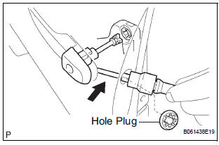
- Remove the hole plug.
- Using a torx socket wrench (T30), loosen the screw and remove the outside handle cover with the door lock key cylinder installed.
15. REMOVE FRONT DOOR WITH MOTOR LOCK ASSEMBLY LH
- Disconnect the door lock connector.
- Using a torx socket wrench (T30), remove the 3 screws and lock.
HINT: Remove the door lock through the service hole.
16. REMOVE FRONT DOOR HANDLE ASSEMBLY OUTSIDE LH
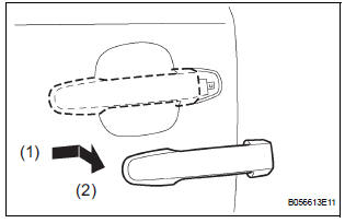
- Pushing and pulling the outside handle in the direction indicated by the arrow mark in the illustration, remove the outside handle.
- Remove the outside handle pads front and rear.
17. REMOVE FRONT DOOR OUTSIDE HANDLE FRAME SUB-ASSEMBLY LH
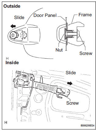
- Using a torx socket wrench (T30), loosen the screw.
- Slide the outside handle frame in the direction
indicated by the arrow mark in the illustration, and
remove it.
HINT: Remove the outside handle frame through the service hole.
- Remove the open rod from the outside handle frame.
18. REMOVE FRONT DOOR CHECK ASSEMBLY LH
- Remove the 2 nuts, bolt and door check.
19. REMOVE FRONT DOOR WEATHERSTRIP LH
- Using a clip remover, disengage the clips and remove the weatherstrip.
HINT: If the clips are damaged, replace them with new ones.
20. REMOVE FRONT DOOR WIRE LH
- Disconnect the wire clips.
- Remove the 2 bolts and wire.
 Front door
COMPONENTS
...
 Adjustment
HINT:
On the RH side, use the same procedures as on the LH
side.
Since a centering bolt is used as a door hinge mounting
bolt on the body side and the door side, the door can not
be adjust ...
Other materials:
Checking and replacing
fuses
If any of the electrical components do not operate, a fuse may
have blown. If this happens, check and replace the fuses as necessary.
Turn the engine switch to the “LOCK” position (vehicles without a
smart key system) or off (vehicles with a smart key system).
Open the fuse box cover.
...
Reassembly
1. INSTALL NO. 1 SEAT CUSHION FRAME SUBASSEMBLY
Install the seat cushion frame with the bolt.
Torque: 20.6 N*m (210 kgf*cm, 15 ft.*lbf)
2. INSTALL RECLINING CONTROL LINK SUBASSEMBLY
Install the reclining control link with the E-ring.
Install the nut.
3. INSTALL RE ...
Vehicle Speed Sensor Malfunction
DTC P0500 Vehicle Speed Sensor Malfunction
DTC P0503 Vehicle Speed Sensor "A" Intermittent / Erratic /
High
DESCRIPTION
The cruise control system uses the same vehicle speed signal that is sent to the
ECM for the SFI system.
If DTC P0500 is detected, perform the diagnosis using th ...
