Toyota Sienna Service Manual: Air Inlet Damper Position Sensor Circuit
DESCRIPTION
This sensor detects the position of the air inlet control servo motor and sends the appropriate signals to the A/C amplifier. The position sensor is built in the air inlet control servo motor.
The position sensor's resistance changes as the air inlet control servo motor arm moves.
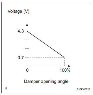
It outputs voltage (5 V) that is input to terminal 1 and terminal 3 via the variable resistor, and then to the A/ C amplifier.
The A/C amplifier determines the arm position based on the input voltage from
the position sensor. 
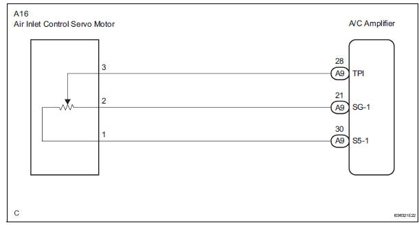
WIRING DIAGRAM
INSPECTION PROCEDURE
1 READ VALUE OF INTELLIGENT TESTER
(a) Connect the intelligent tester to the DLC3.
(b) Turn the ignition switch to the ON position and turn the intelligent tester main switch on.
(c) Select the items below in the DATA LIST, and read the display on the intelligent tester.
DATA LIST / AIR CONDITIONER 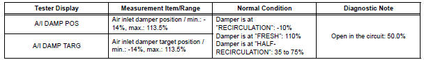
OK: The display is as specified in the normal condition column.
Result 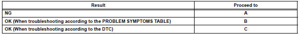

2 INSPECT AIR INLET CONTROL SERVO MOTOR
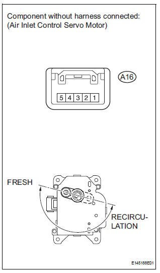
(a) Remove the air inlet control servo motor.
(b) Disconnect the connector from the air inlet control servo motor.
(c) Measure the resistance according to the value(s) in the table below.
Standard resistance 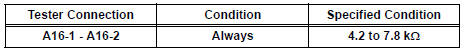
(d) Measure the resistance according to the value(s) in the table below.
Standard resistance 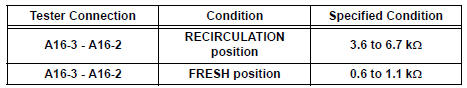
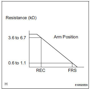
(e) As the air inlet control servo motor moves from RECIRCULATION to FRESH, the resistance decreases gradually without interruption.

3 CHECK HARNESS AND CONNECTOR (AIR INLET CONTROL SERVO MOTOR - A/C AMPLIFIER)
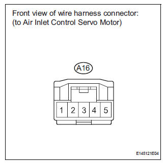
(a) Disconnect the connector from the A/C amplifier.
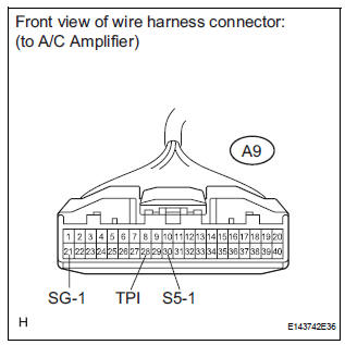
(b) Measure the resistance according to the value(s) in the table below.
Standard resistance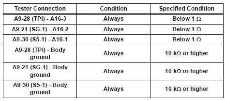

Standard resistance
 Air Mix Damper Position Sensor Circuit (Passenger Side)
DESCRIPTION
This sensor detects the position of the air mix control servo motor (air mix
damper) and sends the
appropriate signals to the A/C amplifier. The position sensor is built in the
a ...
 Air Outlet Damper Position Sensor Circuit
DESCRIPTION
This sensor detects the position of the air outlet control servo motor and
sends the appropriate signals to
the A/C amplifier. The position sensor is built in the air outlet contro ...
Other materials:
Perform zero point calibration of yaw rate and deceleration sensor (when
using sst check wire)
NOTICE:
While obtaining the zero point, do not vibrate the
vehicle by tilting, moving or shaking it and keep it
in a stationary condition. (Do not turn the ignition
switch to the ON position.)
Be sure to do this on a level surface (with an
inclination of less than 1 %).
(a) Proc ...
Diagnosis system
1. DESCRIPTION
When troubleshooting OBD II (On-Board
Diagnostics) vehicles, an intelligent tester
(complying with SAE J1987) must be connected to
the DLC3 (Data Link Connector 3) of the vehicle.
Various data in the vehicle's ECM (Engine Control
Module) can be then read.
& ...
Cellular Phone cannot Send / Receive
INSPECTION PROCEDURE
1 CHECK BLUETOOTH SETTINGS
Check if the Bluetooth settings are correct.
OK:
Bluetooth settings are correct.
2 CHECK CELLULAR PHONE
Check if the cellular phone is Bluetooth compatible.
HINT:
Some versions of Bluetooth compatible cellular phones
may not function ...
