Toyota Sienna Service Manual: Antenna Coil Open / Short
DTC B2784 Antenna Coil Open / Short
DESCRIPTION
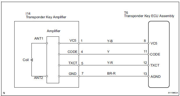
The transponder key coil is built into the transponder key amplifier and receives a key code signal from the transponder chip in the key. This signal is amplified by the amplifier, and output to the transponder key ECU.
|
DTC No. |
DTC Detection Condition |
Trouble Area |
|
B2784 |
Antenna coil open/short |
|
WIRING DIAGRAM
INSPECTION PROCEDURE
1 READ VALUE OF INTELLIGENT TESTER
- Connect the intelligent tester (with CAN VIM) to the DLC3.
- Turn the ignition switch on and turn the intelligent tester main switch on.
- Select ANTENNA COIL in the DATA LIST and read the value displayed on the intelligent tester.
Transponder key ECU:
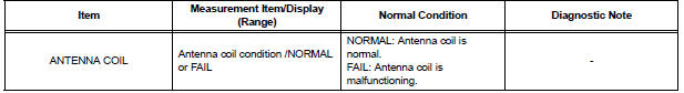
OK: NORMAL (Antenna coil is normal) appears on the screen.
2 CHECK HARNESS AND CONNECTOR (TRANSPONDER KEY ECU ASSEMBLY -TRANSPONDER KEY AMPLIFIER)
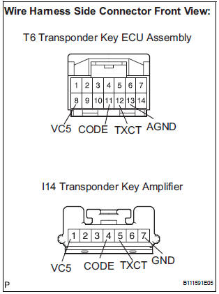
- Disconnect the T6 ECU and I14 switch connectors.
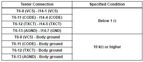
- Measure the resistance according to the value(s) in the table below.
Resistance
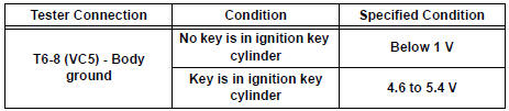
3 INSPECT TRANSPONDER KEY ECU ASSEMBLY
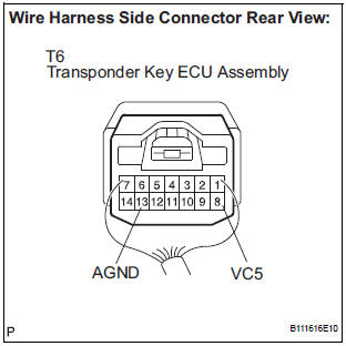
- Reconnect the T6 ECU and I14 amplifier connectors.
- Measure the voltage according to the value(s) in the table below.
Voltage
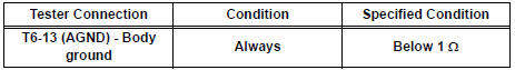
- Measure the resistance according to the value(s) in the table below.
Resistance
REPLACE TRANSPONDER KEY AMPLIFIER
 Push Switch / Key Unlock Warning Switch Malfunction
DTC B2780 Push Switch / Key Unlock Warning Switch Malfunction
DESCRIPTION
This DTC will be output if the transponder key ECU does not detect that the
unlock warning switch is on
even when the ign ...
 Transponder Chip Malfunction
DTC B2793 Transponder Chip Malfunction
DESCRIPTION
This DTC is output when a malfunction is found in the key during the key code
registration or the key code
is not registered normally. Replace t ...
Other materials:
Short to B+ in Front Pretensioner Squib RH Circuit
DTC B0133/62 Short to B+ in Front Pretensioner Squib RH Circuit
DESCRIPTION
The front pretensioner squib RH circuit consists of the center airbag sensor
assembly and the front seat
outer belt assembly RH.
This circuit instructs the SRS to deploy when deployment conditions are met.
DTC B01 ...
Hitch
Trailer hitch assemblies have different weight capacities. Toyota recommends
the use of Toyota hitch/bracket for your vehicle. For details,
contact your Toyota dealer.
If you wish to install a trailer hitch, contact your Toyota
dealer.
Use only a hitch that conforms to the gross trailer w ...
Terminals of ECU
1. CENTER AIRBAG SENSOR ASSEMBLY (w/ Side
Airbag)
2. CENTER AIRBAG SENSOR ASSEMBLY (w/o Side
Airbag)
...
