Toyota Sienna Service Manual: Push Switch / Key Unlock Warning Switch Malfunction
DTC B2780 Push Switch / Key Unlock Warning Switch Malfunction
DESCRIPTION
This DTC will be output if the transponder key ECU does not detect that the unlock warning switch is on even when the ignition switch is on (Under the normal conditions, the unlock warning switch is on when the ignition switch is on).
|
DTC No. |
DTC Detection Condition |
Trouble Area |
|
B2780 |
Unlock warning switch on is not detected when ignition switch is on |
|
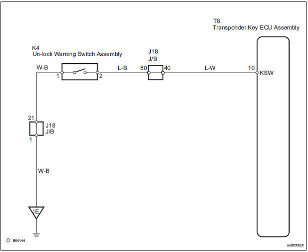
WIRING DIAGRAM
INSPECTION PROCEDURE
1 READ VALUE OF INTELLIGENT TESTER
- Connect the intelligent tester (with CAN VIM) to the DLC3.
- Turn the ignition switch on and turn the intelligent tester main switch on.
- Select KEY SW in the DATA LIST and read the value displayed on the intelligent tester.
Transponder key ECU:
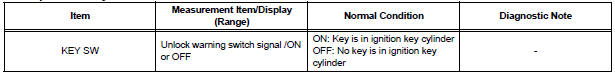
OK: ON (Key is in ignition key cylinder) appears on the screen
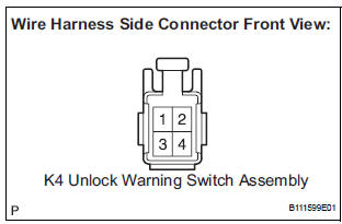
2 INSPECT UNLOCK WARNING SWITCH ASSEMBLY
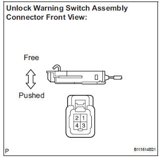
- Remove the unlock warning switch.
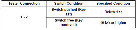
- Measure the resistance according to the value(s) in the table below.
Resistance
3 CHECK HARNESS AND CONNECTOR (TRANSPONDER KEY ECU ASSEMBLY - UNLOCK WARNING SW ASSEMBLY)
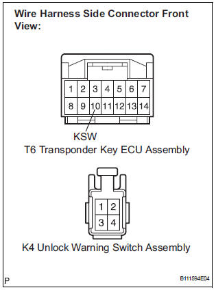
- Disconnect the T6 ECU and K4 switch connectors.
- Measure the resistance according to the value(s) in the table below.
Resistance
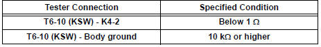
4 CHECK HARNESS AND CONNECTOR (UNLOCK WARNING SW ASSEMBLY - BODY GROUND)
- Measure the resistance according to the value(s) in the table below.
Resistance
REPLACE TRANSPONDER KEY ECU ASSEMBLY
 Diagnostic trouble code chart
If a trouble code is displayed during the DTC check, check
the circuit listed for that code. For details of each code, turn
the page mentioned below the "DTC No" in the DTC chart.
the & ...
 Antenna Coil Open / Short
DTC B2784 Antenna Coil Open / Short
DESCRIPTION
The transponder key coil is built into the transponder key amplifier and
receives a key code signal from
the transponder chip in the key. This sign ...
Other materials:
Compressor Solenoid Circuit
DESCRIPTION
In this circuit, the compressor receives a refrigerant compression demand
signal from the A/C amplifier.
Based on this signal, the compressor changes the amount of compressor output.
WIRING DIAGRAM
INSPECTION PROCEDURE
1 INSPECT A/C COMPRESSOR
(a) Disconnect the A/C com ...
Parking Brake Switch Circuit
DESCRIPTION
This circuit is from the parking brake switch to the radio and navigation
assembly.
WIRING DIAGRAM
INSPECTION PROCEDURE
1 CHECK BRAKE WARNING LIGHT
Check that the brake warning light comes on when the
parking brake is applied and goes off when it is released.
OK:
The ...
Adjustment
1. REMOVE REAR WHEEL
2. ADJUST PARKING BRAKE SHOE CLEARANCE (See
page PB-18)
3. INSTALL REAR WHEEL
Torque: 103 N*m (1,050 kgf*cm, 76 ft.*lbf)
4. INSPECT PARKING BRAKE PEDAL TRAVEL
(a) Slowly depress the parking brake pedal all the way,
and count the number of clicks.
Parking brake pedal trav ...
