Toyota Sienna Service Manual: Diagnostic trouble code chart
If a trouble code is displayed during the DTC check, check the circuit listed for that code. For details of each code, turn the page mentioned below the "DTC No" in the DTC chart.
the "DTC No" in the DTC chart.
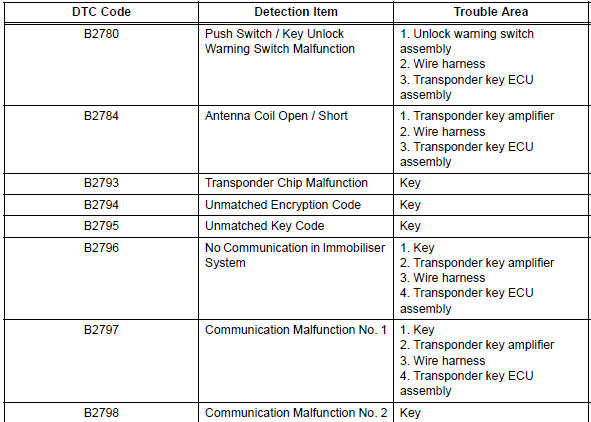
1. TRANSPONDER KEY ECU DIAGNOSTIC TROUBLE CODE CHART
TRANSPONDER KEY ECU
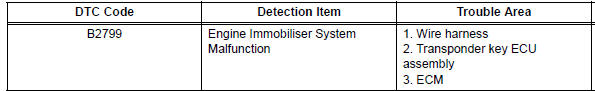
2. ECM DIAGNOSTIC TROUBLE CODE CHART
NOTICE: The DTC for the immobiliser system is specified above. If other codes are output, check the DTC chart for the SFI system.
ECM
- Push Switch / Key Unlock Warning Switch Malfunction
- Antenna Coil Open / Short
- Transponder Chip Malfunction
- Unmatched Encryption Code
- Unmatched Key Code
- No Communication in Immobiliser System
- Engine Immobiliser System Malfunction
 Data list / active test
1. READ DATA LIST
HINT:
Using the DATA LIST displayed on the intelligent tester,
you can read the value of the switch, sensor, actuator,
etc. without parts removal. Reading the DATA LIST as
the f ...
 Push Switch / Key Unlock Warning Switch Malfunction
DTC B2780 Push Switch / Key Unlock Warning Switch Malfunction
DESCRIPTION
This DTC will be output if the transponder key ECU does not detect that the
unlock warning switch is on
even when the ign ...
Other materials:
Removal
1. REMOVE ROOF DRIP SIDE FINISH MOULDING
Put protective tape around the roof drip side finish
moulding.
Using a remover for the roof moulding, disengage of
the clips both in the front and rear ends of the roof
drip side finish moulding and then remove the roof
drip side finish moul ...
Open in Stop Light Switch Circuit
DTC C1249/49 Open in Stop Light Switch Circuit
DESCRIPTION
WIRING DIAGRAM
INSPECTION PROCEDURE
1 CHECK STOP LIGHT SWITCH OPERATION
(a) Check that the stop light comes on when the brake pedal
is depressed and goes off when the brake pedal is
released.
OK
HINT:
Check the stop li ...
Installation
1. INSTALL POWER POINT SOCKET ASSEMBLY
Engage the 2 claws to install the power point socket
assembly.
2. INSTALL QUARTER TRIM FRONT PANEL ASSEMBLY
LH
3. INSTALL BACK DOOR SCUFF PLATE
4. INSTALL BACK DOOR WEATHERSTRIP
5. INSTALL REAR DOOR WEATHERSTRIP LH
6. INSTALL REAR DOOR S ...
