Toyota Sienna Service Manual: Audio terminal
COMPONENTS
REMOVAL
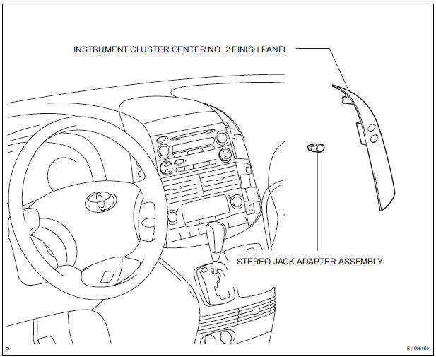
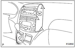
1. REMOVE INSTRUMENT CLUSTER CENTER NO. 2 FINISH PANEL
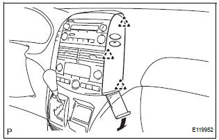
- Using a moulding remover, disengage the 3 clips.
- Disconnect the connector and remove the instrument cluster center No. 2 finish panel.
2. REMOVE STEREO JACK ADAPTER ASSEMBLY
- Disengage the claw and remove the stereo jack adapter assembly.
INSTALLATION
1. INSTALL STEREO JACK ADAPTER ASSEMBLY
- Engage the claw to install the stereo jack adapter assembly.
2. INSTALL INSTRUMENT CLUSTER CENTER NO. 2 FINISH PANEL
- Connect the connector
- Engage the 3 clips to install the instrument cluster center No. 2 finish panel.
 Video terminal
COMPONENTS
REMOVAL
1. REMOVE REAR DOOR SCUFF PLATE LH
2. REMOVE REAR DOOR WEATHERSTRIP LH
3. REMOVE BACK DOOR WEATHERSTRIP
4. REMOVE BACK DOOR SCUFF PLATE
5. REMOVE QUARTER TRIM FRONT PANE ...
 Steering pad switch
COMPONENTS
...
Other materials:
Open in Pump Motor Circuit
DTC C1251/51 Open in Pump Motor Circuit
DESCRIPTION
WIRING DIAGRAM
INSPECTION PROCEDURE
1 PERFORM ACTIVE TEST USING INTELLIGENT TESTER (ABS MOTOR RELAY)
(a) Connect the intelligent tester to the DLC3.
(b) Start the engine.
(c) Select the ACTIVE TEST mode on the intelligent tester.
...
Rear combination light assembly
COMPONENTS
REMOVAL
1. DISCONNECT CABLE FROM NEGATIVE BATTERY
TERMINAL
2. REMOVE REAR COMBINATION LIGHT ASSEMBLY
Remove the 2 bolts.
Disengage the 2 pins and separate the rear
combination light assembly as shown in the
illustration.
Disconnect the connector a ...
Stop light switch
ON-VEHICLE INSPECTION
1. STOP LIGHT SWITCH ASSEMBLY
Check the resistance between the terminals at each
switch position as shown ion the chart.
Resistance
...
