Toyota Sienna Service Manual: Open in Pump Motor Circuit
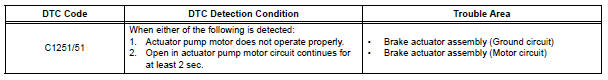
DTC C1251/51 Open in Pump Motor Circuit
DESCRIPTION
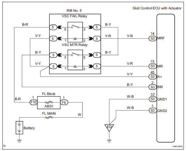
WIRING DIAGRAM
INSPECTION PROCEDURE
1 PERFORM ACTIVE TEST USING INTELLIGENT TESTER (ABS MOTOR RELAY)
(a) Connect the intelligent tester to the DLC3.
(b) Start the engine.
(c) Select the ACTIVE TEST mode on the intelligent tester.
ABS / VSC: 
(d) Check the operation sound of the ABS motor individually when operating it with the intelligent tester.
OK: The operation sound of the ABS motor should be heard.
NOTICE: When replacing the brake actuator assembly, perform zero point calibration (See page BC-70).

REPLACE BRAKE ACTUATOR ASSEMBLY
2 INSPECT SKID CONTROL ECU (GND2 TERMINAL)
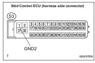
(a) Disconnect the skid control ECU connector.
(b) Measure the resistance according to the value(s) in the table below.
Standard resistance 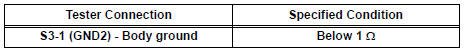
NOTICE: When replacing the brake actuator assembly, perform zero point calibration (See page BC-70).

REPLACE BRAKE ACTUATOR ASSEMBLY
 Open in Stop Light Switch Circuit
DTC C1249/49 Open in Stop Light Switch Circuit
DESCRIPTION
WIRING DIAGRAM
INSPECTION PROCEDURE
1 CHECK STOP LIGHT SWITCH OPERATION
(a) Check that the stop light comes on when the brak ...
 Steering Angle Sensor Zero Point Malfunction
DTC C1290/66 Steering Angle Sensor Zero Point Malfunction
DESCRIPTION
The skid control ECU acquires steering angle sensor zero point every time the
ignition switch is turned to
the ON position an ...
Other materials:
Installation
1. INSTALL BRAKE ACTUATOR
(a) Install the brake actuator assembly with the 2 nuts.
Torque: 5.4 N*m (55 kgf*cm, 48 in.*lbf)
2. INSTALL BRAKE ACTUATOR WITH BRACKET
(a) Install the actuator with bracket with the 3 bolts.
Torque: 20 N*m (199 kgf*cm, 14 ft.*lbf)
NOTICE:
Be careful not to dam ...
Reclining Motor Circuit
DESCRIPTION
The fold seat control ECU receives a switch operation signal from the power
rear no. 2 seat switch and
the fold seat switch, and activates the reclining motor. At this time, the Hall
IC (seatback position sensor)
detects the actuation of the seatback and sends a seatback actuation ...
Installation
1. INSTALL PARK/NEUTRAL POSITION SWITCH ASSEMBLY
(a) Install the park/neutral position switch to the manual
valve shaft.
(b) Temporarily install the 2 bolts.
(c) Place a new lock plate and tighten the nut.
Torque: 6.9 N*m (70 kgf*cm, 61 in.*lbf)
(d) Temporarily install the control ...
