
Toyota Sienna Service Manual: Remote Up / Down Function does not Operate
DESCRIPTION
If the REMOTE UP/DOWN function does not operate, any of the following troubles may be the cause:
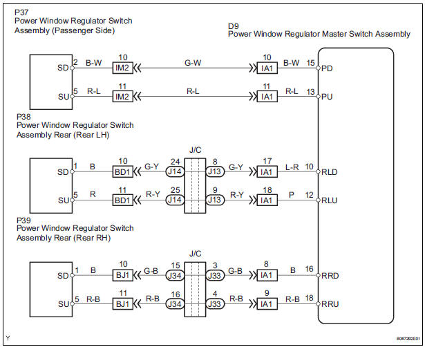
- There is an open or short circuit in the wiring between the power window master switch and the applicable power window regulator switch.
- The power window master switch has a malfunction.
WIRING DIAGRAM
INSPECTION PROCEDURE
1 CHECK POWER WINDOW LOCK SWITCH
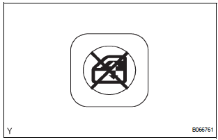
- Push the window lock switch OFF (normal) and check that the remote UP/DOWN function operates.
2 CHECK MANUAL UP/DOWN FUNCTION
- Check that the passenger side door window and slide door windows can be operated via each regulator switch.
3 INSPECT POWER WINDOW MASTER SWITCH
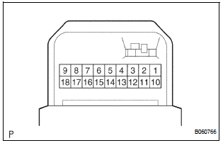
HINT: Inspect the switch with the nonoperational remote function.
- Remove the master switch.
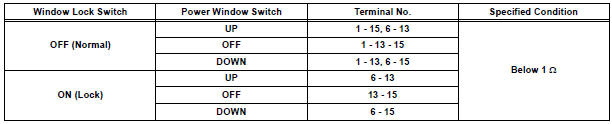
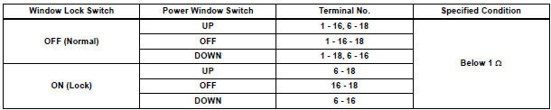
- Check the resistance between the terminals of the master switch when each switch is operated, as shown in the table below.
Standard resistance: Passenger side switch
Rear LH switch

Rear RH switch
REPAIR OR REPLACE HARNESS AND CONNECTOR (MASTER SWITCH - EACH REGULATOR SWITCH)
 Auto Up / Down Function does not Operate
DESCRIPTION
If the AUTO UP/DOWN function does not operate, any of the following troubles
may be the cause:
When the PWR fuse or the power window relay (Marking: PWR) is
replaced with n ...
 Manual Up / Down and Auto Down Function does not Operate on
Driver Side
Manual Up / Down and Auto Down Function does not Operate on
Driver Side
DESCRIPTION
If the manual UP/DOWN function does not operate, no power may be supplied to
the power window
master switch or the power window motor. The power window master switch itself
or the wi ...
Other materials:
Crankshaft Position - Camshaft Position Correlation
DESCRIPTION
Refer to DTC P0335 (See page ES-220).
MONITOR DESCRIPTION
DTC P0016 and P0018
The ECM optimizes the valve timing by using the VVT (Variable Valve Timing)
system to control the intake
camshaft. The VVT system includes the ECM, the Oil Control Valve (OCV) and the
VVT contr ...
Wireless remote control
Vehicles without a smart key system (type A)
Locks all doors
Unlocks all doors
Sounds the alarm
Vehicles without a smart key system (type B)
Locks all doors
Unlocks all doors
Opens and closes the left side power sliding door
Opens and closes the right sid ...
Indicator Circuit
DESCRIPTION
This system has two indicator lights. One of the indicator lights is built
into the fold seat switch. This
indicator light receives power from the fold seat control ECU. It comes on or
blinks when the system
detects that an object is caught or when the seat operation conditions ar ...
