Toyota Sienna Service Manual: Automatic Light Control Sensor Circuit
DESCRIPTION
The Multiplex network body ECU receives the signal from the automatic light control sensor.
HINT: DTC code is output when malfunction of automatic light control sensor or open or short of automatic light control sensor circuit occurs.
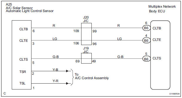
WIRING DIAGRAM
INSPECTION PROCEDURE
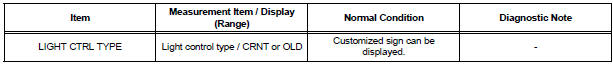
1 READ VALUE OF INTELLIGENT TESTER
- Connect the intelligent tester to DLC3.
- Turn the ignition switch ON and push the intelligent tester main switch ON.
- Select the items below in the DATA LIST, and read the displays on the intelligent tester
BODY NO.1:
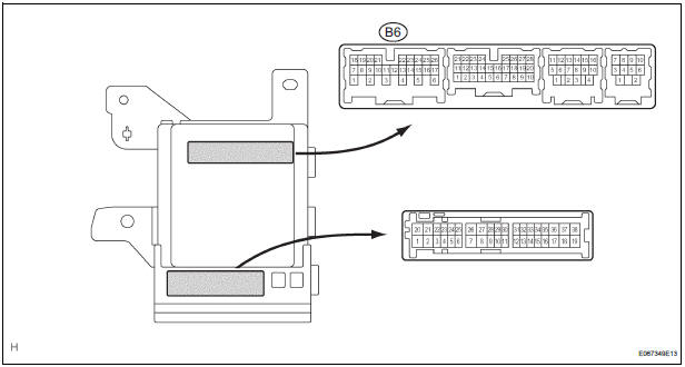
2 CHECK HARNESS AND CONNECTOR (MULTIPLEX NETWORK BODY ECU - AUTOMATIC LIGHT CONTROL SENSOR)
- Check for open or short circuit in the harness and the connector between the terminal 6 of the automatic light control sensor and the terminal B6-6 of the multiplex network body ECU.
- Check for open or short circuit in the harness and the connector between the terminal 3 of the automatic light control sensor and the terminal B6-4 of the multiplex network body ECU.
- Check for open or short circuit in the harness and the connector between the terminal 5 of the automatic light control sensor and the terminal B6-5 of the multiplex network body ECU
3 INSPECT INSTRUMENT PANEL JUNCTION BLOCK ASSEMBLY
- Measure voltage between the terminal B6-4 and the terminal B6-6 of the multiplex network body ECU in the instrument panel junction block assembly.
Voltage

PROCEED TO NEXT CIRCUIT INSPECTION SHOWN IN PROBLEM SYMPTOMS TABLE
 Light Control Switch Circuit
DESCRIPTION
This circuit detects the state of the headlight dimmer switch.
WIRING DIAGRAM
INSPECTION PROCEDURE
1 READ VALUE OF INTELLIGENT TESTER
Connect the intelligent tester to DLC3.
...
 Door Courtesy Switch Circuit
DESCRIPTION
The Multiplex network body ECU detects the condition of the door courtesy
switch assembly.
WIRING DIAGRAM
INSPECTION PROCEDURE
1 READ VALUE OF INTELLIGENT TESTER
Connect the ...
Other materials:
Rear wiper motor and bracket
COMPONENTS
REMOVAL
1. REMOVE REAR WIPER ARM
Remove the rear wiper arm head cap from the rear
wiper arm.
Remove the nut and the rear wiper arm.
2. REMOVE BACK DOOR GARNISH CENTER
3. REMOVE BACK DOOR SIDE GARNISH LH
4. REMOVE POWER BACK DOOR ROD
5. REMOVE BACK DOOR ...
How to proceed with
troubleshooting
HINT:
Use this procedure to troubleshoot the theft deterrent
system.
The intelligent tester should be used in step 2.
1 VEHICLE BROUGHT TO WORKSHOP
2 CUSTOMER PROBLEM ANALYSIS
Interview the customer to confirm the trouble
3 INSPECT COMMUNICATION FUNCTION OF MULTIPLEX COMMUNI ...
Cellular Phone cannot Send / Receive
INSPECTION PROCEDURE
1 CHECK BLUETOOTH SETTINGS
Check if the Bluetooth settings are correct.
OK:
Bluetooth settings are correct.
2 CHECK CELLULAR PHONE
Check if the cellular phone is Bluetooth compatible.
HINT:
Some versions of Bluetooth compatible cellular phones
may not function ...
