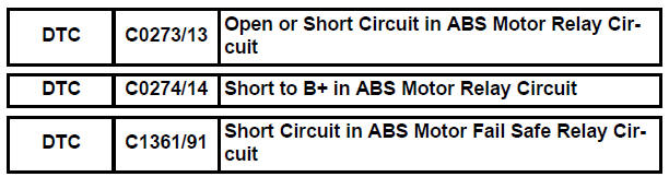
Toyota Sienna Service Manual: Open or Short Circuit in ABS Motor Relay Circuit
DESCRIPTION
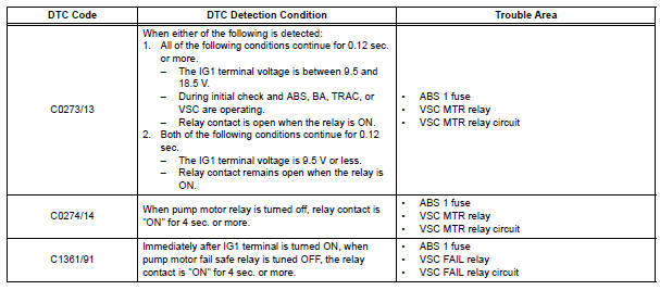
The ABS motor relay supplies power to the ABS pump motor. While the ABS & TRAC & VSC are activated, the ECU switches the ABS motor relay ON and operates the ABS pump motor.
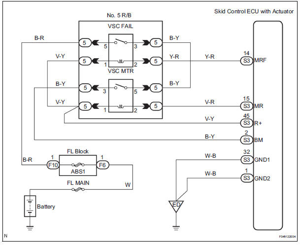
WIRING DIAGRAM
INSPECTION PROCEDURE
1 PERFORM ACTIVE TEST USING INTELLIGENT TESTER (ABS MOTOR RELAY)
(a) Connect the intelligent tester to the DLC3.
(b) Start the engine.
(c) Select the ACTIVE TEST mode on the intelligent tester.
ABS / VSC: 
(d) Check the operation sound of the ABS motor individually when operating it with the intelligent tester.
OK: Operation sound of the ABS motor should be heard.

REPLACE BRAKE ACTUATOR ASSEMBLY
2 INSPECT NO. 5 RELAY BLOCK (POWER SOURCE TERMINAL)
(a) Remove the VSC MTR relay from the No. 5 R/B.
(b) Turn the ignition switch to the ON position.
(c) Measure the voltage according to the value(s) in the table below.
Standard voltage 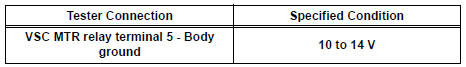

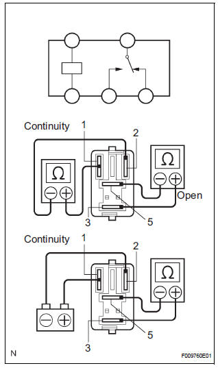
3 INSPECT ABS MOTOR RELAY (VSC MTR)
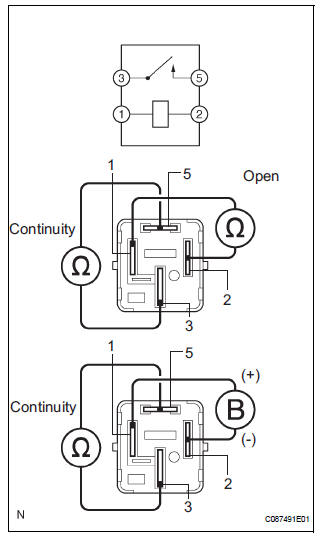
(a) Measure the resistance according to the value(s) in the table below.
Standard resistance 
(b) Apply battery positive voltage between terminals 1 and 2.
(c) Measure the resistance according to the value(s) in the table below.
Standard resistance 

4 CHECK HARNESS AND CONNECTOR (ABS MOTOR RELAY - SKID CONTROL ECU)
(a) Check for open or short circuit in harness and connector between the ABS motor relay and skid control ECU.

5 RECONFIRM DTC
(a) Clear the DTCs.
(b) Drive the vehicle at a speed of 6 km/h (4 mph) or more.
(c) Check if the same DTCs are recorded (See page BC- 82).
Result
HINT:
- The skid control ECU inspects the motor relay circuit when the stop light switch is turned off and the vehicle is running at a speed of 6 km/h (4mph) or more.
- It is suspect that the DTCs output was caused by the poor connection of the connector terminal.

REPLACE BRAKE ACTUATOR ASSEMBLY
6 INSPECT ABS 1 FUSE
(a) Remove the ABS 1 fuse from the FL block.
(b) Measure the resistance according to the value(s) in the table below.
Standard resistance 

7 INSPECT ABS MOTOR RELAY (VSC FAIL)
(a) Measure the resistance according to the value(s) in the table below.
Standard resistance 
(b) Apply battery positive voltage between terminals 1 and 2.
(c) Measure the resistance according to the value(s) in the table below.
Standard resistance 

REPAIR OR REPLACE HARNESS OR CONNECTOR
REPAIR OR REPLACE HARNESS OR CONNECTOR
 SFR Solenoid Circuit
DESCRIPTION
This solenoid goes on when signals are received from the ECU and controls the
pressure acting on the
wheel cylinders to control the braking force.
WIRING DIAGRAM
INSPECTI ...
 Open or Short Circuit in ABS Solenoid Relay Circuit
DESCRIPTION
The ABS solenoid relay is built in the brake actuator assembly. This relay
supplies power to each ABS
solenoid. If the initial check is OK, after the ignition switch is turned to t ...
Other materials:
Installation
1. INSTALL ROOF DRIP SIDE FINISH MOULDING
When exchanging the clips
Remove the tape that remains on the mounting
surface of the vehicle body and then clean the
surface with white gasoline.
Using a heat light, heat up the clip installation
surfaces of the vehicle body and moulding.
...
Reassembly
1. INSTALL POWER SLIDE DOOR TOUCH SENSOR LH
Install the touch sensor with the 4 screws.
Connect the connector.
Fix the wire harness inside the door panel with the
clip.
2. INSTALL REAR DOOR WIRE SUB-ASSEMBLY LH
Install the wire.
NOTICE:
When installing the wire, push the ...
Only Wireless Door Lock Control Function does not Operate
DESCRIPTION
The door control receiver receives a signal from the transmitter and sends
this signal to the multiplex
network body ECU. Then, the multiplex network body ECU controls operation of the
door locks and power
windows.
Then, the power slide door ECU causes the power slide door to o ...
