Toyota Sienna Service Manual: Back Sonar Sensor RH Circuit
DESCRIPTION
An ultrasonic sensor consists of a sensor portion that transmits and receives ultrasonic waves and a preamplifier that amplifies them. The ultrasonic sensor outputs the ultrasonic waves and sends the received signals to the clearance warning ECU.
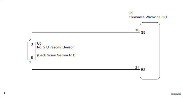
WIRING DIAGRAM
INSPECTION PROCEDURE
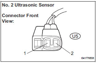
1 INSPECT NO. 2 ULTRASONIC SENSOR
- Remove the No. 2 ultrasonic sensor.
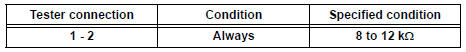
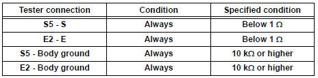
- Measure the resistance according to the value(s) in the table below.
Standard resistance
2 CHECK HARNESS AND CONNECTOR (CLEARANCE WARNING ECU - NO. 2 ULTRASONIC SENSOR)
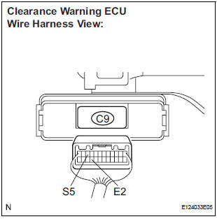
- Disconnect the C9 connector from the clearance warning ECU.
- Disconnect the U5 connector from the No. 2 ultrasonic sensor.
- Measure the resistance according to the value(s) in the table below.
Standard resistance
PROCEED TO NEXT CIRCUIT INSPECTION SHOWN IN PROBLEM SYMPTOMS TABLE
 Back Sonar Sensor LH Circuit
DESCRIPTION
An ultrasonic sensor consists of a sensor portion that transmits and receives
ultrasonic waves and a preamplifier
that amplifies them. The ultrasonic sensor outputs the ultrasonic wave ...
 Front Clearance Sonar Sensor LH Circuit
DESCRIPTION
An ultrasonic sensor consists of a sensor portion that transmits and receives
ultrasonic waves and a preamplifier
that amplifies them. The ultrasonic sensor outputs the ultrasonic wave ...
Other materials:
Data list / active test
1. READ DATA LIST
HINT:
Using the intelligent tester's DATA LIST allows switch,
actuator and other item values to be read without
removing any parts. Reading the DATA LIST early in
troubleshooting is one way to save time.
Connect the intelligent tester with CAN VIM to the
DLC3.
&n ...
Voice is not Recognized
INSPECTION PROCEDURE
1 CHECK NAVIGATION SETTINGS
Enter the "Menu" screen by pressing the "MENU" switch.
Select "Setup
Check that "Voice Recognition Guidance" is not OFF.
OK:
Voice Recognition Guidance is not OFF.
2 CHECK MAP DISC
...
Installation
1. INSTALL TIRE PRESSURE WARNING ECU
(a) Connect the connector to the tire pressure warning
ECU.
(b) Install the tire pressure warning ECU with the screw.
2. INSTALL INSTRUMENT PANEL SAFETY PAD SUBASSEMBLY
HINT:
Refer to the instructions for INSTALLATION of the
instrument panel safety ...
