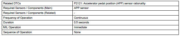
Toyota Sienna Service Manual: Throttle / Pedal Position Sensor / Switch "D" Circuit Range / Performance

HINT:
This DTC relates to the Accelerator Pedal Position (APP) sensor.
DESCRIPTION
Refer to DTC P2120 (See page ES-343).

MONITOR DESCRIPTION
The accelerator pedal position sensor is mounted on the accelerator pedal bracket. The accelerator pedal position sensor has 2 sensor elements and 2 signal outputs: VPA and VPA2. VPA is used to detect the actual accelerator pedal angle (used for engine control) and VPA2 is used to detect malfunctions in VPA.
When the difference between the voltage outputs of VPA and VPA2 deviates from the standard, the ECM determines that the accelerator pedal position sensor is malfunctioning. The ECM turns on the MIL and the DTC is set.
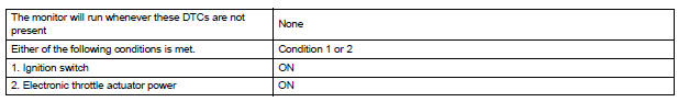
MONITOR STRATEGY
TYPICAL ENABLING CONDITIONS
TYPICAL MALFUNCTION THRESHOLDS

FAIL-SAFE
The accelerator pedal position sensor has 2 (main and sub) sensor circuits. If a malfunction occurs in either of the sensor circuits, the ECM detects the abnormal signal voltage difference between the 2 sensor circuits and switches to limp mode. In limp mode, the functioning circuit is used to calculate the accelerator pedal opening angle to allow the vehicle to continue driving. If both circuits malfunction, the ECM regards the opening angle of the accelerator pedal as being fully closed. In this case, the throttle valve remains closed as if the engine is idling.
If a pass condition is detected and then the ignition switch is turned off, the fail-safe operation stops and the system returns to a normal condition.
WIRING DIAGRAM
Refer to DTC P2120 (See page ES-347).
INSPECTION PROCEDURE
HINT:
Read freeze frame data using the intelligent tester. The ECM records vehicle and driving condition information as freeze frame data the moment a DTC is stored. When troubleshooting, freeze frame data can be helpful in determining whether the vehicle was running or stopped, whether the engine was warmed up or not, whether the air-fuel ratio was lean or rich, as well as other data recorded at the time of a malfunction.
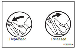
1 READ VALUE OF INTELLIGENT TESTER (ACCEL POS #1 AND ACCEL POS #2)
(a) Connect the intelligent tester to the DLC3.
(b) Turn the ignition switch to the ON position and turn the tester on.
(c) Select the following menu items: DIAGNOSIS / ENHANCED OBD II / DATA LIST / ALL / ACCEL POS #1 and ACCEL POS #2.
(d) Read the values displayed on the tester.
Standard voltage 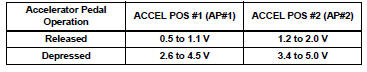


2 CHECK HARNESS AND CONNECTOR (ACCELERATOR PEDAL POSITION SENSOR - ECM)
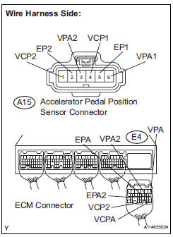
(a) Disconnect the A15 Accelerator Pedal Position (APP) sensor connector.
(b) Disconnect the E4 ECM connector.
(c) Measure the resistance according to the value(s) in the table below.
Standard resistance : 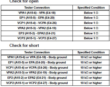
(d) Reconnect the APP sensor connector.
(e) Reconnect the ECM connector.

3 REPLACE ACCELERATOR PEDAL ROD
(a) Replace the accelerator pedal rod assembly (See page ES-502).

4 CHECK WHETHER DTC OUTPUT RECURS (ACCELERATOR PEDAL POSITION SENSOR DTCS)
(a) Connect the intelligent tester to the DLC3.
(b) Turn the ignition switch to the ON position and turn the tester on.
(c) Clear the DTCs (See page ES-39).
(d) Start the engine.
(e) Allow the engine to idle for 15 seconds.
(f) Select the following menu items on the tester: DIAGNOSIS / ENHANCED OBD II / DTC INFO / CURRENT CODES.
(g) Read the DTCs.
Result 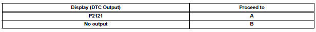


REPLACE ECM (See page ES-498)
 Throttle / Pedal Position Sensor
HINT:
These DTCs relate to the Accelerator Pedal Position (APP) sensor.
DESCRIPTION
HINT:
This ETCS (Electronic Throttle Control System) does not use a throttle cable.
The Accelerator Pedal ...
 Oxygen (A/F) Sensor Signal Stuck
HINT:
Although the DTC titles say oxygen sensor, these DTCs relate to the
Air-Fuel Ratio (A/F) sensor.
Sensor 1 refers to the sensor mounted in front of the Three-Way
Catalytic Convert ...
Other materials:
Purpose of readiness tests
The On-Board Diagnostic (OBD II) system is
designed to monitor the performance of emissionrelated
components, and indicate any detected
abnormalities with DTCs (Diagnostic Trouble Codes).
Since various components need to be monitored in
different driving conditions, the OBD II system ...
Power slide door warning buzzer
INSPECTION
1. INSPECT POWER SLIDE DOOR WARNING BUZZER LH
Check the resistance of the buzzer.
Resistance
If the result is not as specified, replace the buzzer.
NOTICE:
The circuit that causes the buzzer to sound is
built into the slide door ECU, not around the
buzzer.
Direct ...
Inspection
1. INSPECT FRONT STABILIZER LINK ASSEMBLY LH
(a) As shown in the illustration, flip the ball joint stud
back and forth 5 times, before installing the nut.
(b) Using a torque wrench, turn the nut continuously at
a rate of 2 to 4 seconds per 1 turn and take the
torque reading on the 5th tur ...
