Toyota Sienna Service Manual: Disassembly
1. REMOVE CONTROL KNOB SUB-ASSEMBLY (for Manual Air Conditioning System)
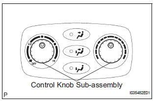
(a) Remove the control knob sub-assembly.
2. REMOVE AIR CONDITIONING CONTROL BULB
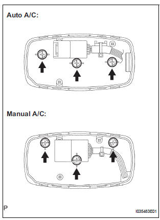
(a) Remove the air conditioning control bulb.
Reassembly
1. INSTALL AIR CONDITIONING CONTROL BULB
2. INSTALL CONTROL KNOB SUB-ASSEMBLY (for Manual Air Conditioning System)
INSTALLATION
1. INSTALL AIR CONDITIONING NO.2 CONTROL ASSEMBLY
 Removal
1. REMOVE AIR CONDITIONING NO.2 CONTROL ASSEMBLY
(a) Release the 4 claw fittings and release the air
conditioning No. 2 control assembly.
(b) Disconnect the connectors and remove the air
con ...
 Integration control and panel
COMPONENTS
...
Other materials:
Reassembly
1. INSTALL FRONT SEAT CUSHION SHIELD LOWER LH
Install the front seat cushion shield lower LH.
2. INSTALL FRONT SEAT CUSHION SHIELD LOWER
RH
3. INSTALL RECLINING ADJUSTER INSIDE COVER LH
Install the reclining adjuster inside cover LH (upper)
with the screw.
4. INSTALL RE ...
Removal
1. REMOVE REAR DOOR SCUFF PLATE LH
2. REMOVE REAR DOOR WEATHERSTRIP LH
3. REMOVE BACK DOOR WEATHERSTRIP
4. REMOVE BACK DOOR SCUFF PLATE
5. REMOVE QUARTER TRIM FRONT PANEL ASSEMBLY LH
6. REMOVE VOLTAGE INVERTER ASSEMBLY
Disconnect the connector.
Remove the 2 bolts and the v ...
Making a call
Once a Bluetooth® phone is registered, you can make a call
using the following procedure:
Dialing
Display the phone screen.
Select the “Dial Pad” tab and enter a phone number.
To delete the input phone number, select
.
For the first digit, you can enter “+” by selecting “&# ...
