Toyota Sienna Service Manual: License plate light assembly
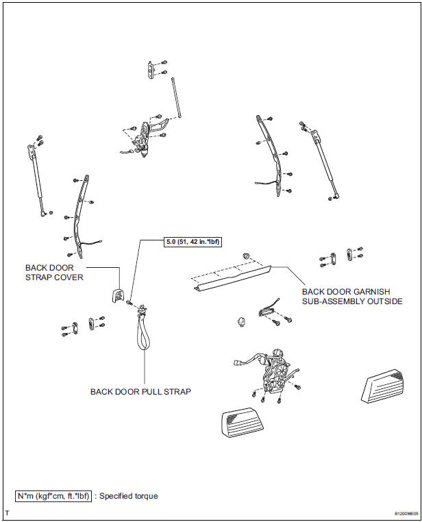
COMPONENTS

REMOVAL
1. REMOVE BACK DOOR GARNISH CENTER
2. REMOVE BACK DOOR SIDE GARNISH LH
3. REMOVE BACK DOOR SIDE GARNISH RH
4. REMOVE BACK DOOR STRAP COVER
5. REMOVE BACK DOOR PULL STRAP
6. REMOVE BACK DOOR TRIM BOARD ASSEMBLY
7. REMOVE BACK DOOR GARNISH SUB-ASSEMBLY OUTSIDE
8. REMOVE LICENSE PLATE LIGHT ASSEMBLY
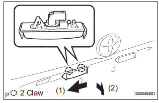
- Release the 2 claw fittings and disconnect the license plate light assembly.
- Disconnect the connector and remove the license plate light assembly.
DISASSEMBLY
1. REMOVE LICENSE PLATE LIGHT LENS GASKET
2. REMOVE LICENSE PLATE LIGHT BULB
- Remove the license plate light bulb and the license plate light socket plug.
- Remove the license plate light bulb from the license plate light socket plug.
3. REMOVE LICENSE PLATE LIGHT SOCKET PLUG
4. REMOVE LICENSE PLATE LIGHT LENS
REASSEMBLY
1. INSTALL LICENSE PLATE LIGHT LENS
2. INSTALL LICENSE PLATE LIGHT SOCKET PLUG
3. INSTALL LICENSE PLATE LIGHT BULB
4. INSTALL LICENSE PLATE LIGHT LENS GASKET
INSTALLATION
1. INSTALL LICENSE PLATE LIGHT ASSEMBLY
2. INSTALL BACK DOOR GARNISH SUB-ASSEMBLY OUTSIDE
3. INSTALL BACK DOOR TRIM BOARD ASSEMBLY
4. INSTALL BACK DOOR PULL STRAP
5. INSTALL BACK DOOR STRAP COVER
6. INSTALL BACK DOOR SIDE GARNISH RH
7. INSTALL BACK DOOR SIDE GARNISH LH
8. INSTALL BACK DOOR GARNISH CENTER
 Back-up light assembly
COMPONENTS
REMOVAL
1. REMOVE BACK DOOR GARNISH CENTER
2. REMOVE BACK DOOR SIDE GARNISH LH
3. REMOVE BACK DOOR SIDE GARNISH RH
4. REMOVE BACK DOOR STRAP COVER SUBASSEMBLY
5. REMOVE BACK D ...
 High mounted stop light assembly
COMPONENTS
REMOVAL
1. REMOVE BACK DOOR GARNISH CENTER (w/ Rear Spoiler)
2. REMOVE REAR SPOILER COVER (w/ Rear Spoiler)
3. REMOVE CENTER STOP LIGHT ASSEMBLY
w/o Rear spoiler:
...
Other materials:
Vanity light
ON-VEHICLE INSPECTION
1. LH VISOR ASSEMBLY
Inspect vanity light resistance.
check that the resistance exists between the
terminal 1 and the terminal 2 when the light is
operated.
Resistance:
OFF (closed):
10 kΩ or higher
ON (opened):
Below 1 Ω
2. RH VISOR ...
Front Occupant Classification Sensor LH Circuit
Malfunction
DTC B1780 Front Occupant Classification Sensor LH Circuit
Malfunction
DESCRIPTION
The front occupant classification sensor LH circuit consists of the occupant
classification ECU and the
front occupant classification sensor LH.
DTC B1780 is recorded when a malfunction is detected in the fron ...
Control Module Performance
DTC P0607 Control Module Performance
DESCRIPTION
The ECM continuously monitors its main and sub CPUs. This self-check ensures
that the ECM is
functioning properly. If outputs from the CPUs are different and deviate from
the standards, the ECM will
illuminate the MIL and set a DTC immediately ...
