Toyota Sienna Service Manual: Back-up Power Source Circuit
DESCRIPTION
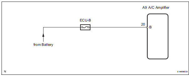
This is the back-up power source for the A/C amplifier. Power is supplied even when the ignition switch is off and is used for diagnostic trouble code memory, etc.
WIRING DIAGRAM
INSPECTION PROCEDURE
1 INSPECT FUSE (ECU-B)
(a) Remove the ECU-B fuse from the engine room junction block.
(b) Measure the resistance according to the value(s) in the table below.
Standard resistance


2 CHECK HARNESS AND CONNECTOR (A/C AMPLIFIER - BATTERY)
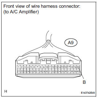
(a) Disconnect the connector from the A/C amplifier.
(b) Measure the voltage according to the value(s) in the table below.
Standard voltage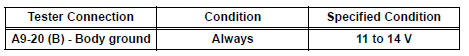

PROCEED TO NEXT CIRCUIT INSPECTION SHOWN IN PROBLEM SYMPTOMS TABLE
 ACC Power Source Circuit
DESCRIPTION
This circuit supplies power to the A/C amplifier and the illumination for the
clock.
WIRING DIAGRAM
INSPECTION PROCEDURE
1 INSPECT FUSE (ECU ACC)
(a) Remove the ECU ACC fuse fr ...

Other materials:
Back Door Courtesy Switch Circuit
DESCRIPTION
The fold seat control ECU receives signals from the back door courtesy switch
and detects the state of the
back door (open/close). If the ECU does not detect that the back door is open,
the seat stowing and return
functions are not available.
WIRING DIAGRAM
INSPECTION PROCED ...
Short to B+ in Rear Curtain Shield Squib RH
Circuit
DTC B1633/82 Short to B+ in Rear Curtain Shield Squib RH
Circuit
DESCRIPTION
The rear curtain shield squib RH circuit consists of the center airbag sensor
assembly and the curtain
shield airbag assembly RH.
The circuit instructs the SRS to deploy when deployment conditions are met.
DTC B ...
System description
1. GENERAL
In conjunction with impact absorbing structure for a
frontal collision, the SRS (Supplemental Restraint
System) driver airbag and front passenger airbag
were designed to supplement seat belts in the event
of a frontal collision in order to help reduce shock to
the head and c ...
