Toyota Sienna Service Manual: Brake Warning Light Remains ON
DESCRIPTION
The BRAKE warning light comes on when the brake fluid is insufficient, the parking brake is applied or the EBD is defective.
WIRING DIAGRAM
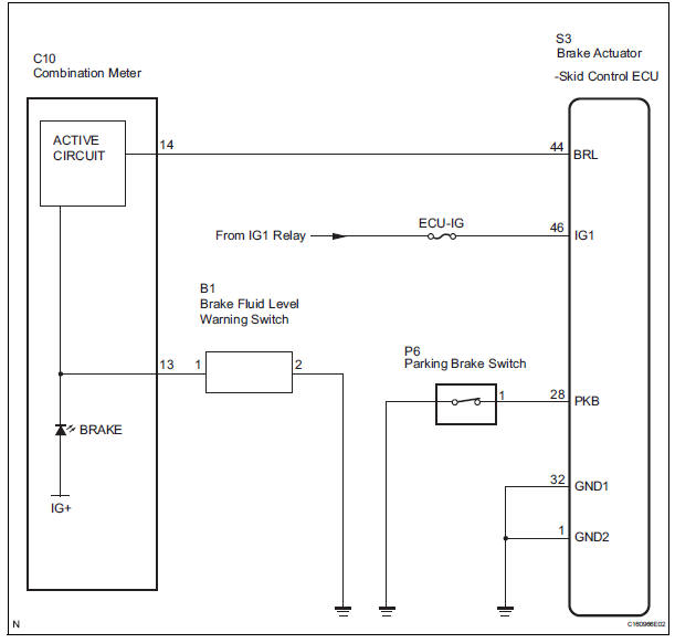
INSPECTION PROCEDURE
HINT: When releasing the parking brake, move the shift lever into the P position in an AT vehicle, and choke in an MT vehicle to hold the vehicle for safety.
1 CHECK BRAKE FLUID LEVEL
(a) Check that the brake fluid level is proper.

2 CHECK DTC
(a) Are the DTC recorded? (See page BC-82)
Result 

REPAIR CIRCUITS INDICATED BY OUTPUT DTCS
3 CHECK BRAKE WARNING LIGHT
ABS / VSC: 
(a) WHEN USING INTELLIGENT TESTER: (1) Connect the intelligent tester to the DLC3.
(2) Start the engine.
(3) Select the item "BRAKE WARN LIGHT" in the ACTIVE TEST and operate the BRAKE warning light on the intelligent tester.
(4) Check that "ON" and "OFF" of the BRAKE warning light are indicated on the combination meter when using the intelligent tester.
OK: Turn the BRAKE warning light on or off in accordance with the intelligent tester.
(b) WHEN NOT USING INTELLIGENT TESTER: (1) Turn the ignition switch off and disconnect the connector from the skid control ECU.
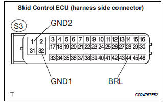
(2) Ground terminal BRL of the skid control ECU.
(3) Turn the ignition switch to the ON position.
(4) Check that the brake warning light.
OK: Turn the light on or off in accordance with the connection of terminal GND and BRL.
NOTICE: When replacing the brake actuator assembly, perform zero point calibration (See page BC-70).

REPLACE BRAKE ACTUATOR ASSEMBLY
4 INSPECT PARKING BRAKE SWITCH
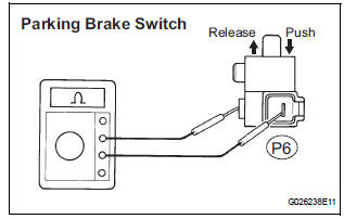
(a) Remove the parking brake switch connector.
(b) Measure the resistance according to the value(s) in the table below.
Standard resistance 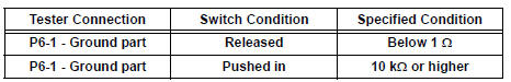

5 CHECK HARNESS AND CONNECTOR (SKID CONTROL ECU - PARKING BRAKE SWITCH)
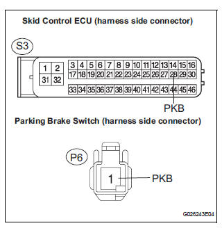
(a) Disconnect the skid control ECU connector and the parking brake switch connector.
(b) Measure the resistance according to the value(s) in the table below.
Standard resistance 
(c) Measure the resistance according to the value(s) in the table below.
Standard resistance 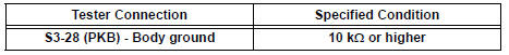
6 INSPECT BRAKE FLUID LEVEL WARNING SWITCH
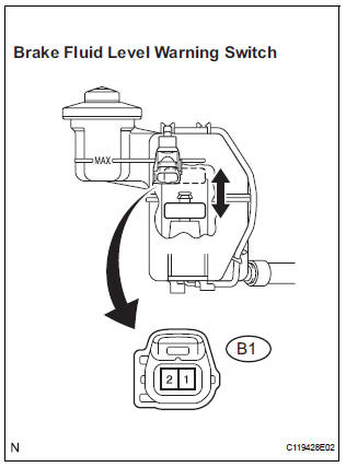
(a) Remove the reservoir tank cap and strainer.
(b) Disconnect the brake fluid level warning switch connector.
(c) Measure the resistance according to the value(s) in the table below.
Standard resistance 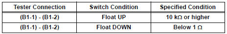

7 CHECK HARNESS AND CONNECTOR (BRAKE FLUID LEVEL WARNING SWITCH - COMBINATION METER)
(a) Disconnect the combination meter connector and the brake fluid level warning switch connector.
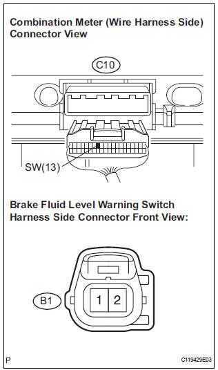
(b) Measure the resistance according to the value(s) in the table below.
Standard resistance 
(c) Measure the resistance according to the value(s) in the table below.
Standard resistance 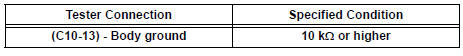

REPAIR OR REPLACE COMBINATION METER ASSEMBLY
 VSC Warning Light does not Come ON
DESCRIPTION
The skid control ECU is connected to the combination meter via CAN and
multiplex communications.
If the skid control ECU stores DTCs to shut down TRAC and VSC operation, the VSC
wa ...
 TRAC OFF Indicator Light Remains ON
DESCRIPTION
The skid control ECU is connected to the combination meter via CAN and
multiplex communications.
When the traction OFF switch is turned on, the TRAC OFF indicator light will
come o ...
Other materials:
Air Intake Control Circuit
DESCRIPTION
The air cleaner is equipped with two inlets, one of which is opened or closed
by the Air Intake Control
Valve (AICV). This system reduces intake noise and increases engine power at
low-to-high engine speed
range.
When the engine is operating in the low-to-mid speed range, this ...
Cruise Main Indicator Light Circuit
DESCRIPTION
The ECM detects a cruise control switch signal and sends it to the
combination meter through CAN
and BEAN. Then the CRUISE main indicator light comes on.
The CRUISE main indicator light circuit uses CAN and BEAN for
communication. If there is a
malfunction in ...
Inspection
1. INSPECT ENGINE COOLANT TEMPERATURE SENSOR
Using an ohmmeter, measure the resistance
between the terminals.
Standard resistance
If the result is as specified, do not replace the
engine coolant temperature sensor.
If the result is not as specified, replace the
engine ...
